Toyota Sienna Service Manual: Installation
1. INSTALL POWER POINT SOCKET ASSEMBLY
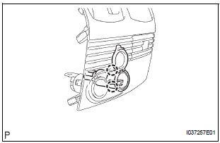
- Engage the 2 claws to install the power point socket assembly.
2. INSTALL INSTRUMENT CLUSTER CENTER LOWER FINISH PANEL SUB-ASSEMBLY
3. INSTALL POSITION INDICATOR HOUSING ASSEMBLY
4. INSTALL SHIFT LEVER KNOB SUB-ASSEMBLY
5. INSTALL INSTRUMENT CLUSTER CENTER NO. 2 FINISH PANEL
6. INSTALL INSTRUMENT CLUSTER CENTER NO. 1 FINISH PANEL
 Removal
1. REMOVE INSTRUMENT CLUSTER CENTER NO. 1 FINISH PANEL
2. REMOVE INSTRUMENT CLUSTER CENTER NO. 2
FINISH PANEL
3. REMOVE SHIFT LEVER KNOB SUB-ASSEMBLY
4. REMOVE POSITION INDICATOR HOUSING ASSEMBLY
...
 Power point socket (for Rear Side)
COMPONENTS
...
Other materials:
Open in Driver Side Squib 2nd Step Circuit
DTC B1181/18 Open in Driver Side Squib 2nd Step Circuit
DESCRIPTION
The driver side squib 2nd step circuit consists of the center airbag sensor
assembly, the spiral cable and
the steering pad.
The circuit instructs the SRS to deploy when deployment conditions are met.
DTC B1181/18 is reco ...
Removal
HINT:
Replace the RH side by the same procedures as the LH side.
1. REMOVE REAR WHEEL
2. REMOVE REAR DISC BRAKE CALIPER ASSEMBLY
LH
(a) Removing the 2 bolts, separate the rear disc brake
caliper assembly LH for disc rear brake type.
NOTICE:
Using a string and so on, hang down the disc
brake ...
Data list
HINT:
Reading the DATA LIST displayed on an intelligent tester
enables values, including those of the switches, sensors,
and actuators, to be checked without removing any
parts. Reading the DATA LIST as the first step in
troubleshooting is one method to shorten diagnostic
time.
NOTICE: ...
