Toyota Sienna Service Manual: Installation
1. INSTALL REAR NO. 2 SEAT ASSEMBLY
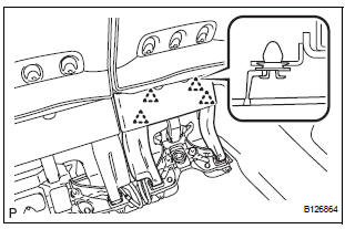
- Lock the seat leg rear to the floor striker.
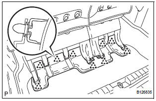
- Lock the seat leg front to the floor striker.
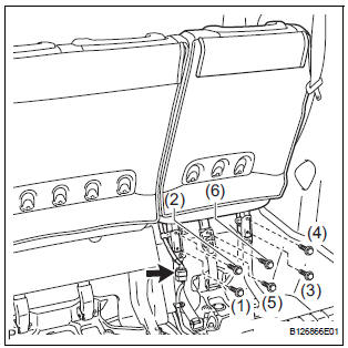
- Install the rear No. 2 seat assembly with the 6 bolts.
Torque: 19 N*m (194 kgf*cm, 14 ft.*lbf)
NOTICE: Tighten the bolts in the order shown in the illustration.
- Connect the connector.
2. INSTALL NO. 2 SEAT HINGE COVER
3. INSTALL REAR SEAT LEG SIDE GARNISH SUBASSEMBLY
- Install 4 new clips to the rear seat leg side garnish sub-assembly.
- Engage the 4 clips and install the rear seat leg side garnish sub-assembly.
4. INSTALL REAR NO. 2 SEAT LEG SIDE GARNISH SUB-ASSEMBLY
- Install 9 new clips to the rear No. 2 seat leg side garnish sub-assembly.
- Engage the 4 clips and install the rear No. 2 seat leg side garnish sub-assembly.
5. CONNECT CABLE TO NEGATIVE BATTERY TERMINAL
6. CHECK POWER REAR NO. 2 SEAT WITH STOWING FUNCTION
7. PERFORM INITIALIZATION
Some systems need initialization after reconnecting the cable to the negative battery terminal.
 Reassembly
1. INSTALL NO. 2 SEAT LEG SUB-ASSEMBLY
Install the No. 2 seat leg sub-assembly with the 3
bolts and nut.
Torque: 19 N*m (194 kgf*cm, 14 ft.*lbf)
NOTICE:
Tighten the bolts and nut ...

Other materials:
Removal
1. REMOVE FRONT WHEEL
2. REMOVE FRONT AXLE HUB LH NUT
HINT:
(See page AH-4)
SST 09930-00010
3. SEPARATE SPEED SENSOR FRONT LH
HINT:
(See page AH-4)
4. SEPARATE FRONT DISC BRAKE CALIPER
ASSEMBLY LH
HINT:
(See page AH-4)
5. REMOVE FRONT DISC
6. SEPARATE TIE ROD ASSEMBLY LH
HINT:
(See pa ...
Rear Air Mix Damper Control Servo Motor Circuit
DESCRIPTION
The rear air mix control servo motor (water valve servo motor) is controlled
by the A/C amplifier.
The rear air mix control servo motor moves the air mix damper by rotating
(normal, reverse) with electrical
power from the A/C amplifier.
WIRING DIAGRAM
INSPECTION PROCEDURE
...
Memory Switch Circuit
DESCRIPTION
When the seat memory switch M1 or M2 is pressed, the position control ECU &
switch (Seat ECU)
transmits a signal of the memorized mirror position to the outer mirror control
ECU. Then, the outer mirror
control ECU drives the mirror motor.
HINT:
The power mirror control syste ...
