Toyota Sienna Service Manual: Installation
1. INSTALL SLIDE DOOR ROLLER ASSEMBLY UPPER
- Apply MP grease to the rotating area of the roller.
- Install the roller with the 2 bolts.
Torque: 13 N*m (130 kgf*cm, 10 ft.*lbf)
2. INSTALL SLIDE DOOR HINGE ASSEMBLY CENTER LH
- Apply MP grease to the rotating areas of the hinge.
- Install the hinge with the 3 bolts.
Torque: 31 N*m (316 kgf*cm, 23 ft.*lbf)
3. INSTALL SLIDE DOOR ROLLER ASSEMBLY LOWER LH
- Apply MP grease to the rotating area of the roller.
- Install the roller with the 3 bolts.
Torque: 31 N*m (316 kgf*cm, 23 ft.*lbf)
4. INSTALL SLIDE DOOR FULL OPEN STOP LOCK ASSEMBLY LH
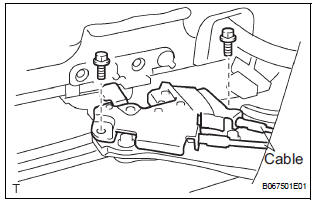
- Apply MP grease to the sliding and rotating areas of the lock.
- Install the lock with the 2 bolts.
Torque: 8.0 N*m (82 kgf*cm, 71 in.*lbf)
- Install the 2 cables.
5. INSTALL SLIDE DOOR RAILS
- Install the rail center with the 3 screws.
Torque: 26 N*m (265 kgf*cm, 19 ft.*lbf)
- Install the rear side rail with the 2 screws.
Torque: 19.5 N*m (200 kgf*cm, 14 ft.*lbf)
- Install the rail upper with the 2 bolts and 2 nuts.
Torque: 10 N*m (102 kgf*cm, 8 ft.*lbf)
- Install the roof headlining
6. INSTALL SLIDE DOOR
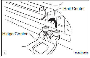
- Put in the slide door hinge center from the rear part of the slide door rail center.
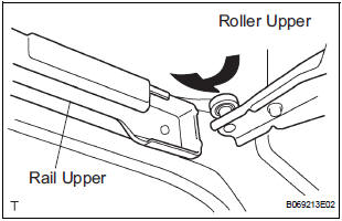
- Move the slide door forward and then put in the slide door roller upper into the cut area of the slide door rail upper.
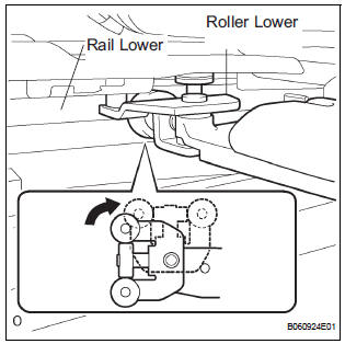
- Rotate the base of the slide door roller lower in the direction indicated by arrow in the illustration and then put in the roller into the cut area of the rail lower of the body.
- Install the open stop with the 2 nuts.
Torque: 7.0 N*m (71 kgf*cm, 62 in.*lbf)
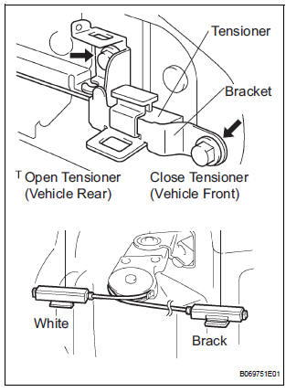
- Connect the open tensioner (color: white) to the bracket center No. 2 on the rear side of the vehicle.
HINT:
- The open tensioner (color: white) should be placed higher than the close tensioner (color: black) at their cross point.
- Be careful for the place where the tensioners are installed.
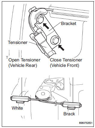
- Install the bracket center No. 2 connected to the
open tensioner (color: white) with the 2 bolts.
Torque: 8.0 N*m (82 kgf*cm, 71 in.*lbf)
- Connect the close tensioner (color: black) to the bracket center No. 1 on the front side of the vehicle.
HINT:
- The close tensioner (color: black) should be placed lower than the open tensioner (color: white) at their cross point.
- Be careful for the place where the tensioner is installed.
- Install the bracket center No. 1 connected to the
close tensioner (color: black) with the 2 bolts.
Torque: 8.0 N*m (82 kgf*cm, 71 in.*lbf)
- Install the end moulding.
- Install the upper rail cushion to the rail upper.
- Install the wire with the bolt.
Torque: 7.0 N*m (71 kgf*cm, 62 in.*lbf)
- Connect the 2 connectors.
 Reassembly
1. INSTALL POWER SLIDE DOOR TOUCH SENSOR LH
Install the touch sensor with the 4 screws.
Connect the connector.
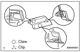
Fix the wire harness inside the door panel with the
clip.
2. INSTALL REA ...
 Slide door lock
INSPECTION
1. INSPECT SLIDE DOOR LOCK REMOTE CONTROL SUB-ASSEMBLY LH
Inspect the resistance of the switch.
Resistance
If the result is not as specified, replace the control
assembly.
...
Other materials:
Disassembly
1. REMOVE FRONT DIFFERENTIAL RING GEAR
(a) Place the match-marks on the ring gear and
differential case.
(b) Remove the 16 bolts.
(c) Using a plastic hammer, tap ring gear to remove it
from the case.
2. REMOVE FRONT DIFFERENTIAL SIDE GEAR
(a) Remove the differential LH case fr ...
Terminals of ECM
1. SFI SYSTEM
HINT:
The standard normal voltage between each pair of the
ECM terminals is shown in the table below. The
appropriate conditions for checking each pair of the
terminals are also indicated.
The check results should be compared with the standard
normal voltage for that pair of ...
Taillight Relay Circuit
DESCRIPTION
The Multiplex network body ECU controls TAIL relay when signal is received
from headlight dimmer
switch assembly.
WIRING DIAGRAM
INSPECTION PROCEDURE
1 PERFORM ACTIVE TEST BY INTELLIGENT TESTER
Connect the intelligent tester to DLC3.
Turn the ignition switch ON and ...
