Toyota Sienna Service Manual: Installation
1. Install air fuel ratio sensor (for bank 2 sensor 1)
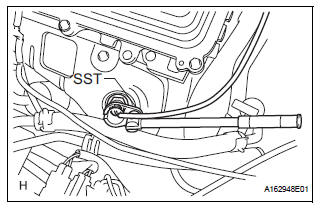
(a) Using SST, install the sensor to the exhaust manifold LH.
SST 09224-00010
Torque: 40 N*m (408 kgf*cm, 30 ft.*lbf) for use with SST 44 N*m (449 kgf*cm, 32 ft.*lbf) for use without SST
HINT:
- Use a torque wrench with a fulcrum length of 30 cm (11.81 in.).
- Make sure that SST and a wrench are connected in a straight line.
(b) Connect the sensor connector
2. INSTALL AIR FUEL RATIO SENSOR (for Bank 1 Sensor 1)
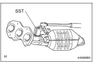
(a) Using SST, install the sensor to the exhaust manifold RH.
SST 09224-00010
Torque: 40 N*m (408 kgf*cm, 30 ft.*lbf) for use with SST
44 N*m (449 kgf*cm, 32 ft.*lbf) for use without SST
HINT:
- Use a torque wrench with a fulcrum length of 30 cm (11.81 in.).
- Make sure that SST and wrench are connected in a straight line.
3. INSTALL EXHAUST MANIFOLD RH
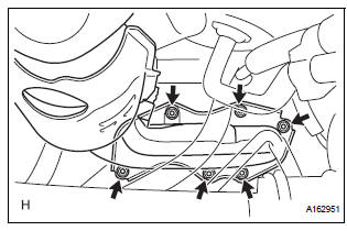
(a) Install the exhaust manifold RH with a new gasket and 6 nuts.
Torque: 21 N*m (214 kgf*cm, 15 ft.*lbf)
(b) Install the exhaust manifold stay with the nut and bolt.
Torque: 35 N*m (357 kgf*cm, 26 ft.*lbf) (c) Connect the air fuel ratio sensor (for Bank 1 Sensor 2) connector.
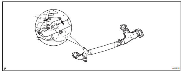
4. INSTALL FRONT EXHAUST PIPE ASSEMBLY
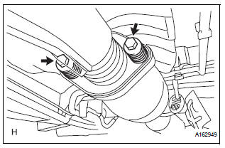
(a) Check compression springs.
(1) Check the compression springs using vernier calipers.
Specified length: 38.86 mm (1.5299 in.)
HINT:
If the result is not as specified, replace the compression spring.
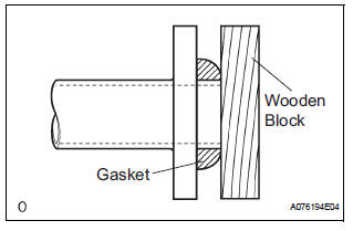
(b) Install the gasket.
(1) Install a new gasket by hand onto the front exhaust pipe assembly.
(2) Using a plastic hammer and wooden block, tap in the new gasket until its surface is flush with the front exhaust pipe.
NOTICE:
|
(c) Install 2 new gaskets to the front exhaust pipe assembly.
(d) Install the front exhaust pipe assembly with the 4 nuts.
Torque: 62 N*m (632 kgf*cm, 46 ft.*lbf)
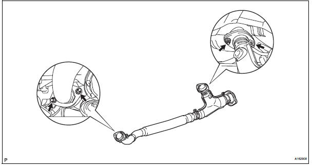
(e) Install the center exhaust pipe assembly with the 2 compression springs and 2 bolts.
Torque: 43 N*m (438 kgf*cm, 32 ft.*lbf) (f) Install the No. 1 exhaust pipe support bracket with the 2 new nuts.
Torque: 21 N*m (214 kgf*cm, 15 ft.*lbf)
(g) Connect the heated oxygen sensor (for Bank 1 sensor 2) connector
5. CONNECT CABLE TO NEGATIVE BATTERY TERMINAL
6. INSPECT FOR EXHAUST GAS LEAK
 Inspection
1. INSPECT AIR FUEL RATIO SENSOR
(a) Measure the resistance of the sensor.
Standard resistance
If the resistance is not as specified, replace the
sensor. ...
 Air fuel ratio sensor (for 4wd)
Components
...
Other materials:
Occupant Classification ECU Malfunction
DTC B1795 Occupant Classification ECU Malfunction
DESCRIPTION
DTC B1795 is recorded when a malfunction is detected in the occupant
classification ECU.
Troubleshoot DTC B1771 first when the DTCs B1771 and B1795 are output
simultaneously.
WIRING DIAGRAM
INSPECTION PROCEDURE
1 CHECK DTC ...
Inspection
1. INSPECT CRANKSHAFT POSITION SENSOR
Using an ohmmeter, measure the resistance
between the terminals.
Standard resistance
NOTICE:
"Cold" and "Hot" mean the temperature of the
coils themselves.
"Cold" is from -10C (14F) to 50C (122F ...
Setup menu
You can adjust the audio system to your desired settings.
Display ÔÇťSetupÔÇŁ screen
Press the ÔÇťSETUPÔÇŁ button to display the ÔÇťSetupÔÇŁ screen.
Select to adjust the settings for operation sounds, screen animation,
etc.
Select to set the voice settings.
Select to adjust th ...
