Toyota Sienna Service Manual: Installation
1. INSTALL HEATED OXYGEN SENSOR (for Bank 2 Sensor 2)
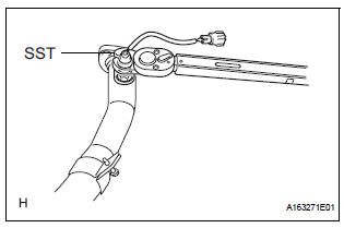
(a) Using SST, install the heated oxygen sensor to the front exhaust pipe.
SST 09224-00010
Torque: 40 N*m (408 kgf*cm, 30 ft.*lbf) for use with SST
44 N*m (449 kgf*cm, 32 ft.*lbf) for use without SST
HINT:
- Use a torque wrench with a fulcrum length of 30 cm (11.81 in.).
- Make sure that SST and a wrench are connected in a straight line.
2. INSTALL FRONT EXHAUST PIPE ASSEMBLY
(a) Install 2 new gaskets to the front exhaust pipe assembly.
(b) Install the front exhaust pipe assembly with the 2 bolts and 2 nuts.
Torque: Bolt 43 N*m (440 kgf*cm, 32 ft.*lbf)
Nut 62 N*m (632 kgf*cm, 46 ft.*lbf)
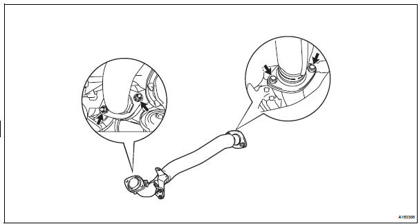
(c) Install the No. 1 exhaust pipe support bracket with 2 new nuts.
Torque: 21 N*m (214 kgf*cm, 15 ft.*lbf)
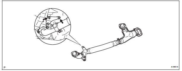
(d) Connect the heated oxygen sensor (for Bank 2 sensor 2) connector.
3. INSTALL HEATED OXYGEN SENSOR (for Bank 1 Sensor 2)
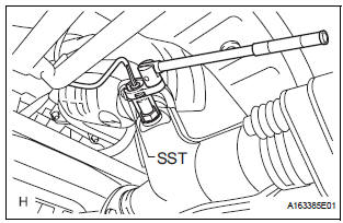
(a) Using SST, install the heated oxygen sensor.
SST 09224-00010
Torque: 40 N*m (408 kgf*cm, 30 ft.*lbf) for use with SST 44 N*m (449 kgf*cm, 32 ft.*lbf) for use without SST
(b) Connect the heated oxygen sensor (for Bank 1 Sensor 2) connector.
HINT:
- Use a torque wrench with a fulcrum length of 30 cm (11.81 in.).
- Make sure that SST and a wrench are connected in a straight line.
4. CONNECT CABLE TO NEGATIVE BATTERY TERMINAL
5. INSPECT FOR EXHAUST GAS LEAK
 Inspection
1. Inspect heated oxygen sensor (for bank 1
sensor 2)
(a) Measure the resistance of the sensor.
Standard resistance
If the resistance is not as specified, replace the
sensor.
2. HEATED OXY ...
 Fuel tank cap
Inspection
1. Inspect fuel tank cap assembly
(A) visually check that the cap and gasket are not
deformed or damaged.
If the result is not as specified, replace the cap
assembly or gasket. ...
Other materials:
Installation
1. INSTALL REAR AXLE BEAM DAMPER
(a) Install the rear axle beam damper to the rear axle
beam assembly.
2. INSTALL REAR AXLE CARRIER BUSH LH
(a) Align the matchmarks on the axle beam assembly
with the 2 notches of a new bushing and temporarily
install the bushing to the rear axle beam assem ...
Initialization
1. ZERO POINT CALIBRATION
NOTICE:
Make sure that the front passenger seat is not
occupied before performing the operation.
HINT:
Perform the zero point calibration and sensitivity check if
any of the following conditions occur.
The occupant classification ECU is replaced.
A ...
Sound Signal Circuit between Radio and Navigation Assembly and
Television Display Assembly
DESCRIPTION
The television display assembly sends an RSE sound signal to the radio and
navigation assembly through
this circuit. The sound signal that has been sent is amplified by the stereo
component amplifier, and then
is sent to the speakers.
If there is an open or short in the circuit ...
