Toyota Sienna Service Manual: Installation
1. Install heated oxygen sensor (for bank 2 sensor 2) (see page ec-34)
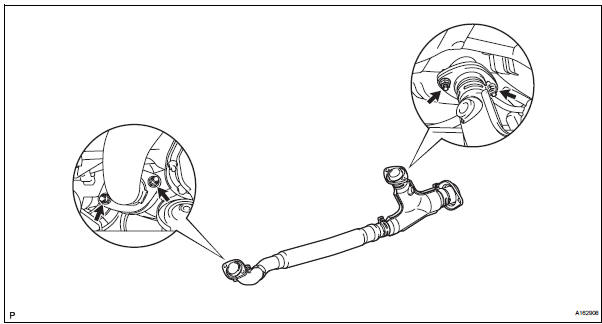
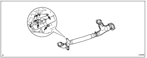
2. Install front exhaust pipe assembly
(a) Install 2 new gaskets to the front exhaust pipe assembly.
(b) Install the front exhaust pipe assembly with the 4 nuts.
Torque: 62 n*m (632 kgf*cm, 46 ft.*Lbf)
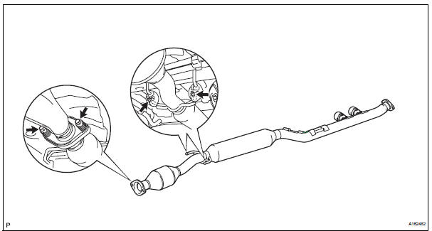
3. INSTALL CENTER EXHAUST PIPE ASSEMBLY
(a) Using a vernier caliper, measure the free length of the compression spring.
Minimum length: 38.86 mm (1.5299 in.)
If the length is less than the minimum, replace the compression spring.
(b) Install a new gasket by hand so that its surface is flush with the front exhaust pipe assembly.
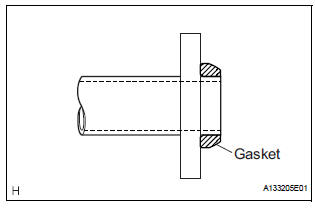
NOTICE:
|
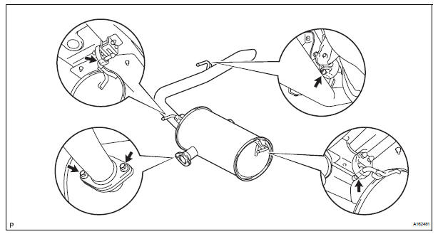
(c) Connect the 2 exhaust pipe supports, and install the center exhaust pipe assembly.
(d) Install the 2 compression springs and 2 bolts.
Torque: 43 N*m (438 kgf*cm, 32 ft.*lbf)
(e) Connect the heated oxygen sensor (for bank 2 sensor 2) connector.
4. INSTALL NO. 1 EXHAUST PIPE SUPPORT BRACKET
(a) Install the No. 1 exhaust pipe support bracket to oil pan sub-assembly with 2 new nuts.
Torque: 21 N*m (214 kgf*cm, 15 ft.*lbf) (b) Loosen the No. 1 exhaust pipe support bracket bolts.
(c) Install the clamp to No. 1 exhaust pipe support bracket.
(d) Retighten the No. 1 exhaust pipe support bracket bolts.
Torque: 21 N*m (214 kgf*cm, 15 ft.*lbf) (e) Install the clamp with the bolt.
Torque: 21 N*m (214 kgf*cm, 15 ft.*lbf)
5. INSTALL TAIL EXHAUST PIPE ASSEMBLY
(a) Install a new gasket to the center exhaust pipe assembly.
(b) Connect the 3 exhaust pipe supports, and install the tail exhaust pipe assembly.
(c) Install 2 new bolts.
Torque: 43 N*m (438 kgf*cm, 32 ft.*lbf)
6. INSTALL HEATED OXYGEN SENSOR (for Bank 1 Sensor 2) (See page EC-36) 7. CONNECT CABLE TO NEGATIVE BATTERY TERMINAL
8. INSPECT FOR EXHAUST GAS LEAK
If exhaust gas is leaking, repair the leak. Replace damaged parts as necessary.
 Removal
1. Disconnect cable from negative battery
terminal
2. REMOVE HEATED OXYGEN SENSOR (for Bank 1
Sensor 2) (See page EC-32)
3. REMOVE TAIL EXHAUST PIPE ASSEMBLY
(a) Remove the 2 bolts.
(b) Discon ...
 Exhaust pipe (for 4wd)
Components
...
Other materials:
Reassembly
1. INSTALL OVERDRIVE DIRECT CLUTCH O-RING
(a) Coat an O-ring with ATF, and install it to the direct
clutch drum.
NOTICE:
Make sure that the O-ring is not twisted or
pinched when it is installed.
2. INSTALL OVERDRIVE DIRECT CLUTCH DRUM SUBASSEMBLY
(a) Coat the direct clutch drum with A ...
Installation
1. INSTALL CENTER AIRBAG SENSOR ASSEMBLY
Check that the ignition switch is off.
Check that the battery negative (-) terminal is
disconnected.
CAUTION:
After disconnecting the negative battery
terminal, wait for at least 90 seconds before
starting the operation.
Temporar ...
Symptom simulation
HINT:
The most difficult case in troubleshooting is when no
problem symptoms occur. In such a case, a thorough
problem analysis must be carried out. A simulation of the
same or similar conditions and environment in which the
problem occurred in the customer's vehicle should be
carried out. No ...
