Toyota Sienna Service Manual: Installation
1. INSTALL HEATED OXYGEN SENSOR (for Bank 2 Sensor 2) (See page EC-39) 2. INSTALL FRONT EXHAUST PIPE ASSEMBLY
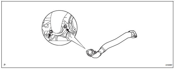
(a) Install a new gasket to the front exhaust pipe assembly.
(b) Install the front exhaust pipe assembly with the 2 nuts.
Torque: 62 N*m (632 kgf*cm, 46 ft.*lbf)
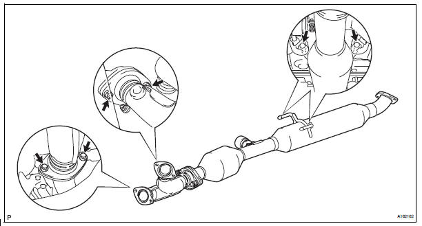
3. V
V(A) install 2 new gaskets to the center exhaust pipe assembly.
(B) connect the 2 exhaust pipe supports, and install the center exhaust pipe assembly.
(C) install 2 new bolts and 2 nuts.
Torque: bolt 43 n*m (438 kgf*cm, 32 ft.*Lbf) nut 62 n*m (632 kgf*cm, 46 ft.*Lbf)
4. Install no. 1 Exhaust pipe support bracket
(a) Install the No. 1 exhaust pipe support bracket to oil pan sub-assembly with 2 new nuts.
Torque: 21 N*m (214 kgf*cm, 15 ft.*lbf) (b) Loosen the No. 1 exhaust pipe support bracket bolts.
(c) Install the clamp to No. 1 exhaust pipe support bracket.
(d) Retighten the No. 1 exhaust pipe support bracket bolts.
Torque: 21 N*m (214 kgf*cm, 15 ft.*lbf) (e) Install the clamp with a new bolt.
Torque: 21 N*m (214 kgf*cm, 15 ft.*lbf)
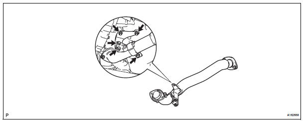
(f) Connect the heated oxygen sensor (for bank 2 sensor 2) connector.
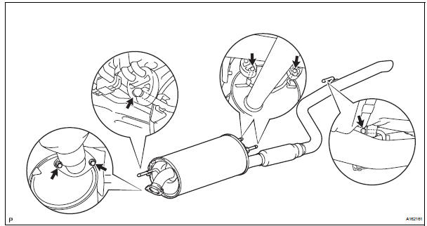
5. INSTALL TAIL EXHAUST PIPE ASSEMBLY
(a) Install a new gasket to the center exhaust pipe assembly.
(b) Connect the 4 exhaust pipe supports, and install the tail exhaust pipe assembly.
(c) Install 2 new bolts.
Torque: 43 N*m (438 kgf*cm, 32 ft.*lbf)
6. INSTALL HEATED OXYGEN SENSOR (for Bank 1 Sensor 2) (See page EC-41)
7. CONNECT CABLE TO NEGATIVE BATTERY TERMINAL
8. INSPECT FOR EXHAUST GAS LEAK
If exhaust gas is leaking, repair the leak. Replace damaged parts as necessary.
 Removal
1. DISCONNECT CABLE FROM NEGATIVE BATTERY
TERMINAL
2. REMOVE HEATED OXYGEN SENSOR (for Bank 1
Sensor 2) (See page EC-38)
3. REMOVE TAIL EXHAUST PIPE ASSEMBLY
(a) Remove the 2 bolts.
(b) Discon ...
 2Gr-fe cooling
...
Other materials:
Slide door lock
INSPECTION
1. INSPECT SLIDE DOOR LOCK REMOTE CONTROL SUB-ASSEMBLY LH
Inspect the resistance of the switch.
Resistance
If the result is not as specified, replace the control
assembly.
2. INSPECT SLIDE DOOR LOCK REMOTE CONTROL SUB-ASSEMBLY RH
Inspect the resistance of the swit ...
Route cannot be Calculated
INSPECTION PROCEDURE
1 CHECK MAP DISC
Check that the map disc is not deformed or cracked.
OK:
No deformations or cracks on map disc.
2 SET DESTINATION
Set another destination and check if the system can
calculate the route correctly.
OK:
Route can be correctly calculated.
NO ...
Installation
1. INSTALL SPARK PLUG
(a) Install the 6 spark plugs.
Torque: 18 N*m (183 kgf*cm, 13 ft.*lbf)
2. INSTALL IGNITION COIL ASSEMBLY
(a) Install the 6 ignition coils with the 6 bolts.
Torque: 10 N*m (102 kgf*cm, 7 ft.*lbf)
(b) Connect the 6 ignition coil connectors.
3. INSTALL NO. 1 SUR ...
