Toyota Sienna Service Manual: Installation
1. INSTALL TRANSMISSION CONTROL CABLE ASSEMBLY
(a) Pull in the control cable to the body.
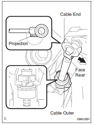
(b) Install the cable end, as shown in the illustration.
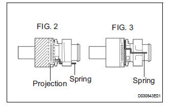
(c) When installing the transmission control cable assembly on the shift lever plate, place the projection of the shift cable downward to fit in the groove of the shift lever plate (FIG.2) Confirm that the spring in the shift cable outer has moved to the position (FIG.3) shown in the illustration.
Confirm that the shift cable is installed on the shift lever plate properly.
NOTICE:
- To prevent torsion of the inner cable, the projection on the eye end should face rear.
- Push the cable end to the bottom of the pin.
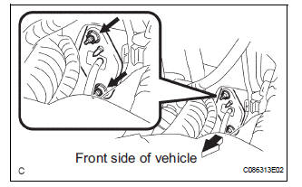
d) Install the transmission control cable assembly and 2 nuts.
Torque: 12 N*m (122 kgf*cm, 9 ft.*lbf)
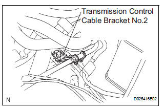
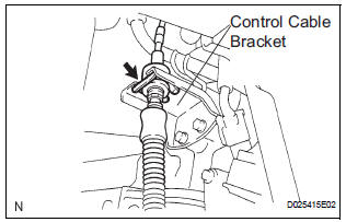
(e) Connect the transmission control cable assembly to the transmission control cable bracket No.2.
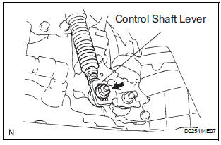
(f) Temporarily install the transmission control cable assembly to the control shaft lever with the nut.
(g) Install the transmission control cable assembly and clip to the bracket.
2. INSTALL INSTRUMENT CLUSTER FINISH PANEL SUB-ASSEMBLY CENTER
HINT: (See page IP-15)
3. ADJUST SHIFT LEVER POSITION
HINT: (See page AX-155)
4. INSPECT SHIFT LEVER POSITION
HINT: (See page AX-155)
 Adjustment
1. INSPECT SHIFT LEVER POSITION
(a) When shifting from P to R position only with ignition
switch ON and brake pedal, make sure that the
shifting lever moves smoothly and can be
moderately operated ...
Other materials:
Installation
1. INSTALL VANE PUMP ASSEMBLY
(a) Temporarily install the bolt to the vane pump
assembly.
(b) Install the vane pump assembly.
(c) Temporarily install the bolt (B).
(d) Using SST, tighten the 2 bolts.
SST 09249-63010
Torque:Without SST
43 N*m (439 kgf*cm, 32 ft.*lbf)
With SST
29 ...
Disassembly
1. REMOVE FRONT DIFFERENTIAL RING GEAR
(a) Place matchmarks on the front differential ring gear
and differential case.
(b) Remove the 14 bolts.
(c) Using a plastic hammer, tap on the front differential
ring gear to remove it from the case.
2. REMOVE FRONT DIFFERENTIAL CASE FRONT TA ...
Check and replace ecu
NOTICE: • The connector should not be disconnected from
the ECU. Perform the inspection from the
backside of the connector on the wire harness
side.
• When no measuring condition is specified,
perform the inspection with the engine stopped
and the ignition switch on.
• Che ...
