Toyota Sienna Service Manual: Installation
1. INSTALL TRANSFER ASSEMBLY
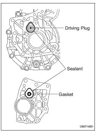
(a) Apply sealant 1281 to the transaxle assembly and transfer assembly in continuous beaded from of 1.2 mm diameter as shown in the illustration.
NOTICE:
- Wipe any grease off from the attaching surfaces.
- Install it within 10 minutes after applying the sealant.
- Sealant stuck on the gasket, case oil seal and driving plug may cause oil leakage and seizure due to oil shortage. Care must be taken.
(b) Install the transfer assembly to the transaxle assembly with the 2 bolts and 6 nuts.
Torque: 69 N*m (700 kgf*cm, 51 ft.*lbf)
NOTICE:
- Check that the gasket is installed to the transfer assembly before installing them to the transaxle assembly.
- Install the transfer assembly to the transaxle assembly without tilting.
- When moving the transfer assembly, do not hold the oil seal on the both sides.
2. INSTALL AUTOMATIC TRANSMISSION WITH TRANSFER
HINT: (See page AX-167)
3. INSTALL ENGINE AND TRANSAXLE
HINT: (See page EM-44)
4. INSTALL TRANSFER DRAIN PLUG
(a) Install the transfer drain plug with a new drain gasket.
Torque: 49 N*m (500 kgf*cm, 36 ft.*lbf)
5. INSTALL NO. 2 TRANSFER CASE PLUG
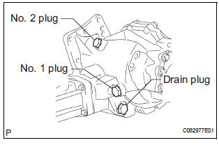
(a) Install the No. 2 transfer case plug with a new No. 2 gasket.
Torque: 49 N*m (500 kgf*cm, 36 ft.*lbf)
6. INSTALL NO. 1 TRANSFER CASE PLUG
(a) Add oil up to 0 to 5 mm below the lower side of the plug hole.
Oil quantity: 0.9 L (0.95 US qts, 0.71 lmp. qts)
HINT: When adding oil, pour it slowly.
(b) Install the No. 1 transfer case plug with a new No. 1 gasket.
Torque: 49 N*m (500 kgf*cm, 36 ft.*lbf)
7. INSPECT AND ADJUST FRONT WHEEL ALIGNMENT
HINT: (See page SP-4)
8. CHECK ABS SPEED SENSOR SIGNAL
HINT: (See page BC-3)
 Removal
1. REMOVE ENGINE AND TRANSAXLE
HINT:
(See page EM-26)
2. REMOVE AUTOMATIC TRANSMISSION WITH
TRANSFER
HINT:
(See page AX-164)
3. REMOVE NO. 1 TRANSFER CASE PLUG
(a) Remove the No. 1 transfe ...
 Transfer unit
COMPONENTS
...
Other materials:
List of storage features
Auxiliary boxes
Cup holders
Door pockets
Bottle holders
Glove boxes
Console box (if equipped)
WARNING
Do not leave glasses, lighters or spray cans in the storage
spaces, as this
may cause the following when cabin temperature becomes high:
Glas ...
Warning Buzzer Malfunction
DTC P1575 Warning Buzzer Malfunction
DESCRIPTION
The ABS & traction actuator (skid control ECU) receives an alarm demand
signal from the ECM and
operates the skid control buzzer. The buzzer sounds to warn that the distance
between the vehicle in front
and your own vehicle is decreasing.
...
Operation check
1. ILLUMINATED ENTRY SYSTEM OPERATION CHECK
The illuminated entry system is explained below:
Turn the ignition switch OFF, close all the doors,
and set them in the lock condition.
Unlock any door and open any other doors and
check that the room light comes on. Close ...
