Toyota Sienna Service Manual: Installation
1. INSTALL FRONT DRIVE SHAFT ASSEMBLY LH
(a) Coat the spline of the inboard joint shaft assembly with ATF.
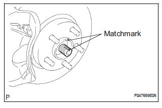
(b) Align the shaft splines and install the drive shaft assembly with a brass bar and hammer.
NOTICE:
- Set the snap ring with the opening side facing down.
- Be careful not to damage the drive shaft dust cover, boot and oil seal.
- Move the drive shaft assembly while keeping it level.
2. INSTALL FRONT DRIVE SHAFT ASSEMBLY RH (for 2WD)
(a) Using a screwdriver, install a new bearing bracket hole snap ring.
NOTICE: Do not damage the oil seal and boot.
(b) Install the bolt.
Torque: 32 N*m (330 kgf*cm, 24 ft.*lbf)
3. INSTALL FRONT DRIVE SHAFT ASSEMBLY RH (for 4WD)
HINT: Install the RH side using the same procedures as for the LH side.
NOTICE:
- Set the snap ring with the opening side facing downward.
- Be careful not to damage the transaxle case oil seal, inboard joint boot and drive shaft dust cover.
4. INSTALL FRONT AXLE ASSEMBLY LH
(a) Install the drive shaft assembly LH to the front axle assembly LH.
NOTICE:
- Be careful not to damage the outboard joint boot.
- Be careful not to damage the speed sensor rotor.
5. INSTALL NO. 1 FRONT SUSPENSION ARM SUBASSEMBLY LOWER LH
(a) Install the lower ball joint to the front suspension arm sub-assembly lower with the bolt and nuts.
Torque: 127 N*m (1,300 kgf*cm, 94 ft.*lbf)
6. INSTALL TIE ROD END SUB-ASSEMBLY LH
(a) Install the tie rod end to the steering knuckle with the nut.
Torque: 49 N*m (500 kgf*cm, 36 ft.*lbf) (b) Install a new cotter pin.
NOTICE: If the holes for the cotter pin are not aligned, tighten the nut up to 60° further.
7. INSTALL SPEED SENSOR FRONT LH
(a) Install the speed sensor to the steering knuckle with the bolt.
Torque: 8.0 N*m (82 kgf*cm, 71 in.*lbf)
NOTICE: Prevent foreign matter from adhering to the speed sensor.
(b) Install the flexible hose and the speed sensor to the shock absorber with the bolt and set the clip of sensor on knuckle.
Torque: 19 N*m (192 kgf*cm, 14 ft.*lbf)
NOTICE:
- Be careful not to damage the speed sensor.
- Prevent foreign matter from adhering to the speed sensor.
- Do not twist the sensor wire when installing the speed sensor.
8. INSTALL FRONT STABILIZER LINK ASSEMBLY LH
(a) Install the stabilizer link assembly LH with the nut.
Torque: 74 N*m (755 kgf*cm, 55 ft.*lbf)
HINT: If the ball joint turns together with nut. use a hexagon (6 mm) wrench to hold the stud.
9. INSTALL FRONT AXLE HUB LH NUT
(a) Using a socket wrench (30 mm), install a new axle hub LH nut.
Torque: 294 N*m (3,000 kgf*cm, 217 ft.*lbf) (b) Using a chisel and hammer, stake the axle hub LH nut.
10. INSTALL FRONT WHEEL Torque: 103 N*m (1,050 kgf*cm, 76 ft.*lbf)
11. ADD AUTOMATIC TRANSAXLE FLUID
HINT:
- for U151E: (See page AX-123)
- for U151F: (See page AX-123)
12. ADD TRANSFER OIL (for 4WD)
HINT: (See page TF-3)
13. INSPECT AND ADJUST FRONT WHEEL ALIGNMENT
HINT: (See page SP-4)
14. CHECK ABS SPEED SENSOR SIGNAL
HINT:
- for ANTI-LOCK BRAKE SYSTEM: (See page BC-3)
- for VEHICLE STABILITY CONTROL SYSTEM: (See page BC-72)
 Reassembly
1. INSTALL FRONT DRIVE SHAFT BEARING
(a) Using SST and a press, install a new front drive
shaft bearing.
SST 09710-30021 (09710-03141), 09527-10011
NOTICE:
Bearing should be completely instal ...
 Rear drive shaft (for 4wd)
COMPONENTS
...
Other materials:
Passenger Airbag ON/OFF Indicator Circuit
Malfunction
DTC B1152/28 Passenger Airbag ON/OFF Indicator Circuit
Malfunction
DESCRIPTION
The passenger airbag ON/OFF indicator circuit consists of the center airbag
sensor assembly and
passenger airbag ON/OFF indicator.
This circuit indicates the operation condition of the front passenger airbag,
t ...
Installation
1. INSTALL AMPLIFIER ANTENNA ASSEMBLY
Engage the 16 clamps to install the amplifier
antenna assembly.
Install the 3 bolts.
Connect the connectors.
2. INSTALL ROOF HEADLINING ASSEMBLY
3. INSTALL ANTENNA ASSEMBLY WITH HOLDER
Install the antenna assembly ...
Driving Position Memory Switch Circuit (w/ Memory)
DESCRIPTION
The seat memory switch sends signals to the outer mirror control ECU LH via
the multiplex
communication system to memorize a given seat position. This memory system does
not use a position
sensor. The seat position is detected by counting pulses that are output when
the motor tu ...
