Toyota Sienna Service Manual: Intake system
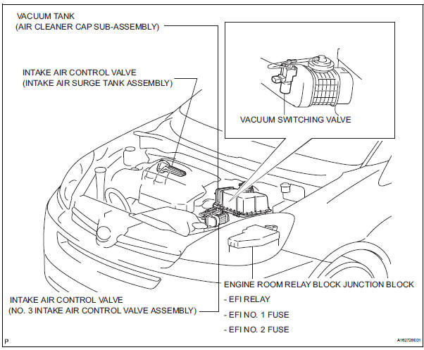
Parts location
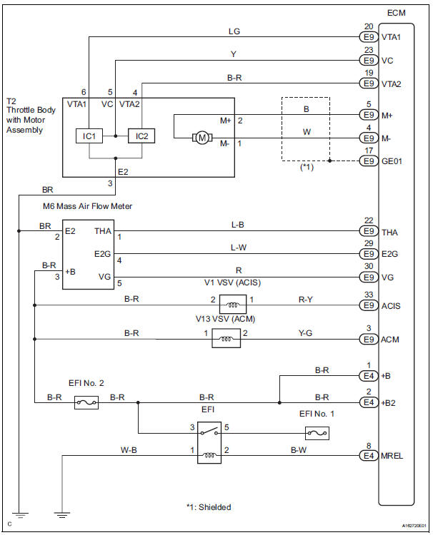
System diagram
 2Gr-fe intake
...
 Intake air control valve
Components
...
Other materials:
Voice Guidance does not Function
INSPECTION PROCEDURE
1 CHECK NAVIGATION SYSTEM SETTING
Enter the "Menu" screen by pressing the "MENU" switch.
Select "Volume".
Check that "OFF" is not selected.
OK:
"OFF" is not selected
2 CHECK NAVIGATION SETTING
...
Terminals of ECU
1. RADIO RECEIVER (10 SPEAKER SYSTEM)
*1: with Rear Seat Entertainment System
2. RADIO RECEIVER (6 SPEAKER SYSTEM)
*1: with Rear Seat Entertainment System
*2: without Rear Seat Entertainment System
3. STEREO COMPONENT AMPLIFIER
4. TELEVISION DISPLAY ASSEMBLY ...
Turning the high beam on/off manually
Switching to low beam
Pull the lever to the original
position.
Switching to high beam
Turn the light switch to the
position.
The Automatic High Beam can be operated when
The engine switch is in the “ON” position (vehicles without a smart key
system)
or IGNITION ON mode (vehicl ...
