Toyota Sienna Service Manual: Internal Control Module Random Access Memory (RAM) Error
DTC P0604 Internal Control Module Random Access Memory (RAM) Error
DESCRIPTION
The ECM continuously monitors its own internal memory status, internal circuits, and output signals transmitted to the throttle actuator. This self-check ensures that the ECM is functioning properly. If any malfunction is detected, the ECM sets the appropriate DTC and illuminates the MIL.
The ECM memory status is diagnosed by internal mirroring of the main CPU and the sub CPU to detect Random Access Memory (RAM) errors. The two CPUs also perform continuous mutual monitoring. The ECM illuminates the MIL and sets a DTC if: 1) outputs from the two CPUs are different or deviate from the standards, 2) the signals sent to the throttle actuator deviate from the standards, 3) a malfunction is found in the throttle actuator supply voltage, and 4) any other ECM malfunction is found.

MONITOR STRATEGY
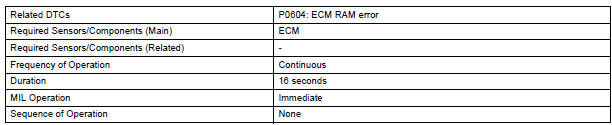
TYPICAL ENABLING CONDITIONS

TYPICAL MALFUNCTION THRESHOLDS
ECM RAM errors:

INSPECTION PROCEDURE
Read freeze frame data using the intelligent tester. Freeze frame data records the engine condition when malfunctions are detected. When troubleshooting, freeze frame data can help determine if the vehicle was moving or stationary, if the engine was warmed up or not, if the air-fuel ratio was lean or rich, and other data from the time the malfunction occurred.
1 CHECK ANY OTHER DTCS OUTPUT (IN ADDITION TO DTC P0604)
- Connect the intelligent tester to the DLC3.
- Turn the ignition switch to the ON position.
- Turn the tester on.
- Select the following menu items: DIAGNOSIS / ENHANCED OBD II / DTC INFO / CURRENT CODES.
- Read DTCs.
Result

REPLACE ECM
 System Voltage
DTC P0560 System Voltage
MONITOR DESCRIPTION
The battery supplies electricity to the ECM even when the ignition switch is
off. This power allows the
ECM to store data such as DTC history, freeze ...
 ECM / PCM Processor
DTC P0606 ECM / PCM Processor
DESCRIPTION
The ECM continuously monitors its internal processors (CPUs), A/F sensor
transistors and heated oxygen
sensor (HO2S) transistors. This self-check ensures ...
Other materials:
Rear Occupant Classification Sensor LH Collision
Detection
DTC B1787 Rear Occupant Classification Sensor LH Collision
Detection
DESCRIPTION
DTC B1787 is output when the occupant classification ECU receives a collision
detection signal sent by
the rear occupant classification sensor LH if an accident occurs.
DTC B1787 is also output when the front s ...
Illumination Circuit
DESCRIPTION
Power is supplied to the radio and navigation assembly and steering pad
switch illumination when the
light control switch is in the TAIL or HEAD position.
WIRING DIAGRAM
INSPECTION PROCEDURE
NOTICE:
The vehicle is equipped with an SRS (Supplemental Restraint System) such as t ...
Adjustment
HINT:
On the RH side, use the same procedures as on the LH side.
1. INSPECT SLIDE DOOR PANEL SUB-ASSEMBLY LH
Check that the clearance is within the standard
range.
Standard
2. ADJUST SLIDE DOOR PANEL SUB-ASSEMBLY LH
Using the SST, horizontally and vertically adjust the
...
