Toyota Sienna Service Manual: Jam Protection Function Activates During Power Slide Door LH Operation
DESCRIPTION
- It may be caused by ill-fitting slide door, faulty touch sensor or faulty pulse sensor.
- The power slide door ECU activates the slide motor to open / close the power slide door, thus controlling the power slide door operation. For jam and foreign object detection, the power slide door system uses the pulse sensor built into the slide motor and the touch sensor installed in the front side of the slide door.
- When the touch sensor comes in contact with an object while the slide door is closing, the resistance of the touch sensor changes which is monitored by the power slide door ECU. If a change in resistance is detected, the ECU will judge it to be a jam and foreign object detection in the direction that the power slide door is moving and reverse slide motor rotation. The touch sensor operates only while the slide door is closing. It does not operate while the slide door is opening.
- The pulse sensor detects changes in the operating speed of the slide door while the slide door is operating. When the sensor detects a change in the operating speed, the pulse from the sensor also changes, which is monitored by the power slide door ECU. If there is a pulse change detected, the ECU will judge it to be a jam and foreign object detection in the direction that the power slide door is moving and reverse slide motor rotation.
- If a jam and foreign object detection by the touch sensor and the pulse sensor has occurred 2 or more consecutive times and if the 2nd or most recent detection has occurred during closing, then the power slide door ECU will cancel automated slide door operation and switch the slide door to manual operation mode (not electrically controlled). In order to return the power slide door system to normal operation mode, perform either of the following: manually close the slide door fully or press the satellite switch for the power slide door or the power slide door control switch again (reset operation).
WIRING DIAGRAM
INSPECTION PROCEDURE
1 CHECK DTC
- Check for DTC B2224. DTC B2224 indicates a pulse sensor malfunction.
- Without code outputs, proceed to A.
- With code outputs, proceed to B.
2 VISUALLY CHECK
- Check for foreign objects on the sliding area.
3 MANUAL OPERATION
- Turn off* the power slide door main switch in order to
locate the area where reverse operation has been
triggered.
* OFF is the position where orange paint on the top of the switch does not appear.
- Move the slide door manually, and check to make sure no obstacles are present (no extra resistance) around the reverse operation area and that the slide door smoothly operates.
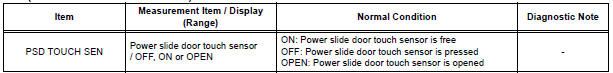
4 READ VALUE OF INTELLIGENT TESTER
- Using the intelligent tester, check the DATA LIST for proper functioning of power slide door touch sensor LH.
OK (Power slide door ECU LH):
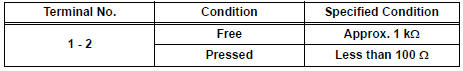
5 INSPECT POWER SLIDE DOOR TOUCH SENSOR LH
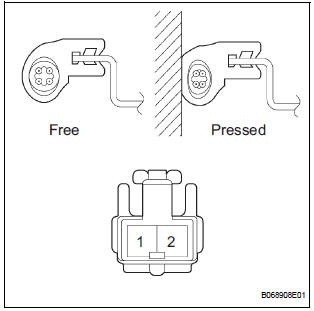
- Inspect the resistance of the sensor.
Resistance
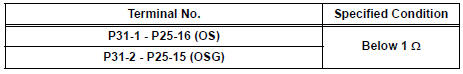
6 CHECK WIRE HARNESS (POWER SLIDE DOOR TOUCH SENSOR LH - POWER SLIDE DOOR ECU LH)
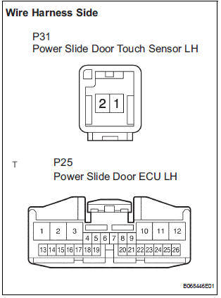
- Disconnect the P31 sensor and P25 ECU connectors.
- Check the resistance between the wire harness side connectors.
Resistance (Check for open circuit)
REPLACE POWER SLIDE DOOR ECU LH
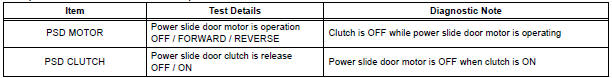
7 PERFORM ACTIVE TEST BY INTELLIGENT TESTER
- Select the ACTIVE TEST and then check that the power slide door control motor and clutch LH operates.
HINT: During the ACTIVE TEST, the intelligent tester sends a signal to the power slide door ECU LH to drive the motor and clutch. If the motor and clutch operate, the motor and clutch itself and the wire harness between the motor and clutch and the power slide door ECU are considered to be functioning normally.
OK (Power slide door ECU LH):
8 INSPECT SLIDE DOOR CONTROL MOTOR AND CLUTCH ASSEMBLY LH
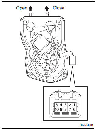
- Remove the motor and clutch.
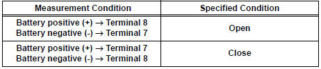
- Connect the battery positive (+) lead to terminal 3 and battery negative (-) terminal lead to terminal 2.
- Apply battery voltage to the terminals and check the motor operation.
OK
- Check the resistance of the clutch terminals.
Resistance

- Reinstall the motor and clutch with the connector connected.
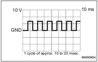
- Check the pulse of the pulse sensor.
- Using an oscilloscope, check the pulse generated when the door is manually opened and closed.
Reference
HINT: A cycle of the pulse changes between approx. 10 to 20 msec. according to the speeds that the slide door is moving.
NOTICE: When disconnecting the control motor and clutch, initialize the power slide door system
9 CHECK WIRE HARNESS (SLIDE DOOR CONTROL MOTOR AND CLUTCH - POWER SLIDE DOOR ECU)
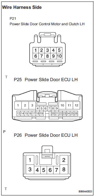
- Disconnect the P21 motor and clutch, the P25 and P26 ECU connectors.
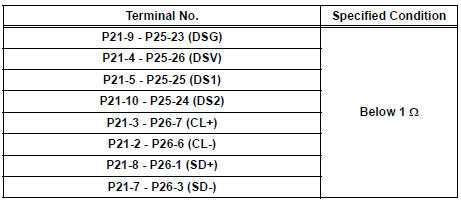
- Check the resistance between the wire harness side connectors.
Resistance (Check for open circuit)
REPLACE POWER SLIDE DOOR ECU LH
 Power Slide Door RH does not Operate When Using Inside / Outside
Handle
Power Slide Door RH does not Operate When Using Inside / Outside
Handle
DESCRIPTION
The inside / outside handles have the ability to control operation
of the power slide door. Pulling either
handle transmits a request signal to the power slide door ECU RH, ...
 Jam Protection Function Activates During Power Slide Door RH
Operation
Jam Protection Function Activates During Power Slide Door RH
Operation
DESCRIPTION
It may be caused by ill-fitting slide door, faulty touch sensor or
faulty pulse sensor.
The power slide door ECU activates the slide motor to open / close
the power ...
Other materials:
Inspection
1. Inspect generator clutch pulley
(a) Hold the center of the pulley, and confirm that the
outer ring turns counterclockwise and does not turn
clockwise.
If the result is not as specified, replace the clutch
pulley.
2. Remove generator drive end frame bearing
(a) Check that the bear ...
Problem symptoms table
POWER BACK DOOR SYSTEM
Symptom
Suspected Area
Power back door does not operate when switch* is
pressed (* Switch indicates the satellite switch for
power back door)
ECU-B fuse
Power back door main switch
Satellite switch
Power back door tou ...
Short to GND in Side Squib RH Circuit
DTC B0112/41 Short to GND in Side Squib RH Circuit
DESCRIPTION
The side squib RH circuit consists of the center airbag sensor assembly and
the front seat side airbag
assembly RH.
The circuit instructs the SRS to deploy when deployment conditions are met.
DTC B0112/41 is recorded when a sh ...
