Toyota Sienna Service Manual: Key Lock-in Prevention Function does not Work Properly (Manual Operation and Operation Interlocked with Key are Active)
DESCRIPTION
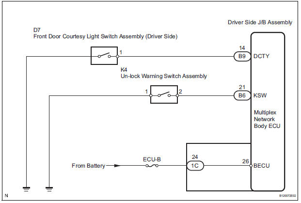
The un-lock warning switch turns ON when the key is inserted in the ignition key cylinder. The courtesy light switch turns ON when the driver side door is opened. These 2 switches are monitored by the body ECU.
In order to prevent the key from being locked in, the body ECU controls door locking operation according to the conditions of these switches so that the doors are not locked.
WIRING DIAGRAM
INSPECTION PROCEDURE
1 INSPECT FUSE (ECU-B)
- Remove ECU-B fuse from engine room junction block.
- Measure the resistance.
Standard resistance: Below 1 Ω
2 READ VALUE OF DATA LIST
- Using the intelligent tester, check that the un-lock warning switch signal is output when the switch is operated.
BODY (Multiplex network body ECU)

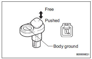
3 INSPECT UN-LOCK WARNING SWITCH ASSEMBLY
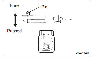
- Remove the un-lock warning switch.
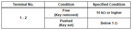
- Measure the resistance according to the value(s) in the table below.
Standard resistance
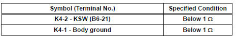
4 CHECK HARNESS AND CONNECTOR (UN-LOCK WARNING SWITCH ASSEMBLY - DRIVER SIDE J/B)
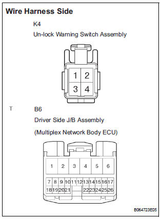
- Disconnect the K4 switch and B6 body ECU connectors.
- Measure the resistance according to the value(s) in the table below.
Standard resistance
REPLACE DRIVER SIDE JUNCTION BLOCK ASSEMBLY (MULTIPLEX NETWORK BODY ECU)
5 READ VALUE OF DATA LIST
- Using the intelligent tester, check that the driver side door courtesy light switch signal s output when the switch is operated.
BODY (Multiplex network body ECU)

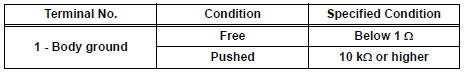
6 INSPECT FRONT DOOR COURTESY LIGHT SWITCH ASSEMBLY (DRIVER SIDE)
- Remove the courtesy light switch.
- Measure the resistance according to the value(s) in the table below.
Standard resistance
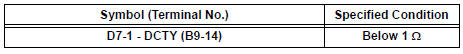
7 CHECK HARNESS AND CONNECTOR (FRONT DOOR COURTESY LIGHT SWITCH - DRIVER SIDE J/B)
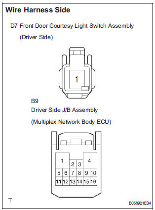
- Disconnect the D7 switch and B9 body ECU connectors.
- Measure the resistance according to the value(s) in the table below.
Standard resistance
REPLACE DRIVER SIDE JUNCTION BLOCK ASSEMBLY (MULTIPLEX NETWORK BODY ECU)
 All Doors cannot be Locked / Unlocked at Once
DESCRIPTION
The body ECU receives a switch signal from the master switch, the door
control switch, the driver door
key cylinder and the passenger door key cylinder and then drives the door lock
...
 Only Back Door cannot be Opened
DESCRIPTION
With power back door: The signal for manual locking/unlocking operation of
the driver/passenger side
door and the signal for locking/unlocking operation interlocked with the driver
s ...
Other materials:
Diagnosis Circuit
DESCRIPTION
DTC output mode is set by connecting terminals TC and CG of the DLC3.
DTCs are displayed by blinking the SRS warning light.
HINT:
When each warning light stays blinking, a ground short in the
wiring of terminal TC of the DLC3 or an
internal ground short in each ECU is ...
Disassembly
1. REMOVE STOP LIGHT SWITCH ASSEMBLY
(a) Turn the stop light switch assembly
counterclockwise and remove the stop light switch
assembly.
(b) Remove the stop light switch mounting adjuster
from the brake pedal support sub-assembly.
2. REMOVE STOP LIGHT SWITCH CUSHION
(a) Remove the stop ligh ...
DTC check / clear
HINT:
Illustrations may differ from the actual vehicle depending
on the device settings and options. Therefore, some
detailed areas may not be shown exactly the same as on
the actual vehicle.
If the system cannot enter the diagnostic mode, inspect all AVC-LAN
communication ...
