Toyota Sienna Service Manual: Light Sensor Circuit Malfunction
DTC B1244 Light Sensor Circuit Malfunction
DESCRIPTION
This DTC is output when failure in the light sensor circuit is detected.
|
DTC No. |
DTC Detection Condition |
Trouble Area |
|
B1244 |
|
|
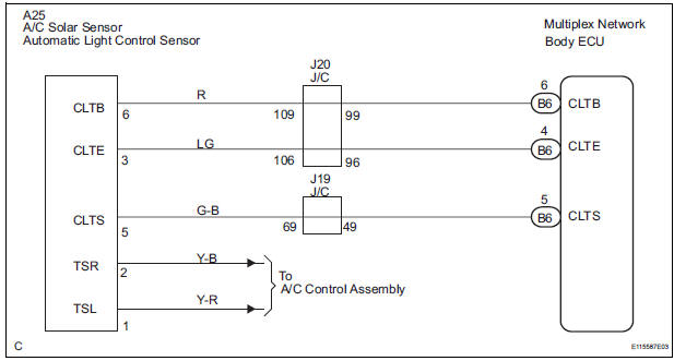
WIRING DIAGRAM
INSPECTION PROCEDURE
1 READ VALUE OF INTELLIGENT TESTER
- Connect the intelligent tester to DLC3.
- Turn the ignition switch ON and push the intelligent tester main switch ON.
- Select the items below in the DATA LIST, and read the displays on the intelligent tester
BODY NO.1:

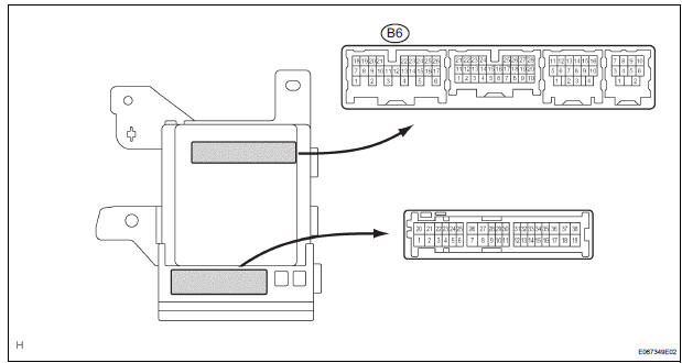
2 CHECK HARNESS AND CONNECTOR (MULTIPLEX NETWORK BODY ECU - AUTOMATIC LIGHT CONTROL SENSOR)
- Check for open or short circuit in the harness and the connector between the terminal 6 of the automatic light control sensor and the terminal B6-6 of the multiplex network body ECU.
- Check for open or short circuit in the harness and the connector between the terminal 3 of the automatic light control sensor and the terminal B6-4 of the multiplex network body ECU.
- Check for open or short circuit in the harness and the connector between the terminal 5 of the automatic light control sensor and the terminal B6-5 of the multiplex network body ECU
3 INSPECT AUTOMATIC LIGHT CONTROL SENSOR
- Measure voltage between the terminal 3 and the terminal 5 of the automatic light control sensor
Standard

4 INSPECT INSTRUMENT PANEL JUNCTION BLOCK ASSEMBLY
- Measure voltage between the terminal B6-6 and the terminal B6-4 of the multiplex network body ECU in the instrument panel junction block assembly.
Voltage

REPLACE AUTOMATIC LIGHT CONTROL SENSOR
 Diagnostic trouble code chart
1. DTC CHECK
If a malfunction code is displayed during the DTC check ,
check the suspected area listed for that code in the table
below, and proceed to the appropriate page.
DIAGNOSTIC TROUBLE COD ...
 Ignition Switch Circuit
DESCRIPTION
The Multiplex network body ECU receives the ACC and IG signals from the
ignition switch.
WIRING DIAGRAM
INSPECTION PROCEDURE
1 READ VALUE OF INTELLIGENT TESTER
Connect the in ...
Other materials:
Memory Switch Circuit
DESCRIPTION
When the seat memory switch M1 or M2 is pressed, the position control ECU &
switch (Seat ECU)
transmits a signal of the memorized mirror position to the outer mirror control
ECU. Then, the outer mirror
control ECU drives the mirror motor.
HINT:
The power mirror control syste ...
Adjustment procedure
Manual seat
Seat position adjustment lever
Seatback angle adjustment lever
Vertical height adjustment lever (driver’s side only)
Lumbar support adjustment switch (driver’s side only)*
*: If equipped
Power seat
Seat position adjustment switch
Seatback angle a ...
Diagnostic trouble code chart
If a trouble code is displayed during the DTCs check (sensor
check), check the circuit listed for the code in the table below
(Proceed to the page given for that circuit).
AIR CONDITIONING SYSTEM
HINT:
*1: If the cabin temperature is approximately -18.6°C (-
3.7°F) or lo ...
