Toyota Sienna Service Manual: Master Reset/ Voice Processing Device ON Error
DTC 01-DD Master Reset
DTC 01-E1 Voice Processing Device ON
DESCRIPTION
|
DTC No. |
DTC Detection Condition |
Trouble Area |
| 01-DD *1 | The device that should be the master has been disconnected after the engine starts. |
|
| 01-E1 *2 | The AMP device records that the AMP output does not function even while the source device is operating. |
HINT:
- *1: This code may be stored if the engine is started and the ignition switch is turned to the START position again.
- *2: Even if no fault is present, this trouble code may be stored depending on the battery condition or engine start voltage.
NOTICE:
- Before starting troubleshooting, be sure to clear DTCs to erase codes stored due to the reasons described in the HINT above. Then, check for DTCs and troubleshoot according to the output DTCs.
- The radio and navigation assembly is the master unit.
- Be sure to clear and recheck DTCs after the inspection is completed to confirm that no DTCs are output.
INSPECTION PROCEDURE
NOTICE: Be sure to read DESCRIPTION before performing the following procedures.
1 CHECK RADIO AND NAVIGATION ASSEMBLY POWER SOURCE CIRCUIT
Refer to the radio and navigation assembly power source circuit.
If the power source circuit is operating normally, proceed to the next step
2 INSPECT RADIO AND NAVIGATION ASSEMBLY
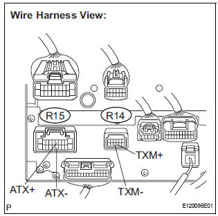
- Disconnect the radio and navigation assembly connectors.
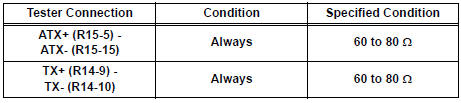
- Measure the resistance according to the value(s) in the table below.
Standard resistance
3 IDENTIFY THE COMPONENT WHICH HAS STORED THIS CODE
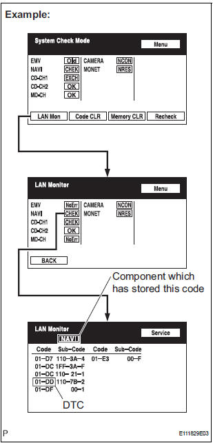
- Enter the diagnostic mode.
- Press the "LAN Mon" switch to change to "LAN Monitor" mode.
- Identify the component which has stored this code.
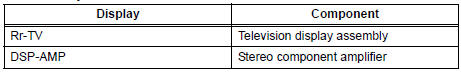
Component Table:
HINT: "NAVI" is the component which has stored this code in the example shown in the illustration.
4 CHECK HARNESS AND CONNECT
HINT: For details of the connectors, refer to "TERMINALS OF ECU".
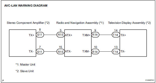
- Referring to the AVC-LAN wiring diagram below, check the AVC-LAN circuit between the radio and navigation assembly and the component which has stored this code.
- Disconnect all connectors between the radio and navigation assembly and the component which has stored this code.
- Check for an open or short in the AVC-LAN circuit between the radio and navigation assembly and the component which has stored this code.
OK: There is no open or short circuit.
5 REPLACE RADIO AND NAVIGATION ASSEMBLY
- Replace the radio and navigation assembly with a normal one and check if the same problem occurs again.
OK: Same problem does not occur.
END
 Transmission Error
DTC 01-DC Transmission Error
DESCRIPTION
DTC No.
DTC Detection Condition
Trouble Area
01-DC
*1
Transmission to component shown by sub-code failed.
(Detec ...
 Master Error
DTC 01-DF Master Error
DESCRIPTION
DTC No.
DTC Detection Condition
Trouble Area
01-DF
*1
The device with a display fails and the master is
switch ...
Other materials:
Removal
HINT:
Use the same procedures for the RH side and LH side.
The procedures listed below are for the LH side.
1. PRECAUTION
CAUTION:
Be sure to read "PRECAUTION" thoroughly before servicing.
2. DISCONNECT CABLE FROM NEGATIVE BATTERY
TERMINAL
CAUTION:
Wait for 90 se ...
Installation
1. REMOVE FRONT SEAT INNER BELT ASSEMBLY
HINT:
Refer to the instructions for reassembly of the front
seat assembly (for flat type).
Refer to the instructions for reassembly of the front
seat assembly (for manual seat).
Refer to the instructions for reassembly of the fr ...
Horn
To sound the horn, press on or
close to the mark.
WARNINGCaution while driving
Do not adjust the steering wheel while driving.
Doing so may cause the driver to mishandle the vehicle and cause an
accident,
resulting in death or serious injury.
After adjusting the steeri ...
