Toyota Sienna Service Manual: Memory Switch Circuit
DESCRIPTION
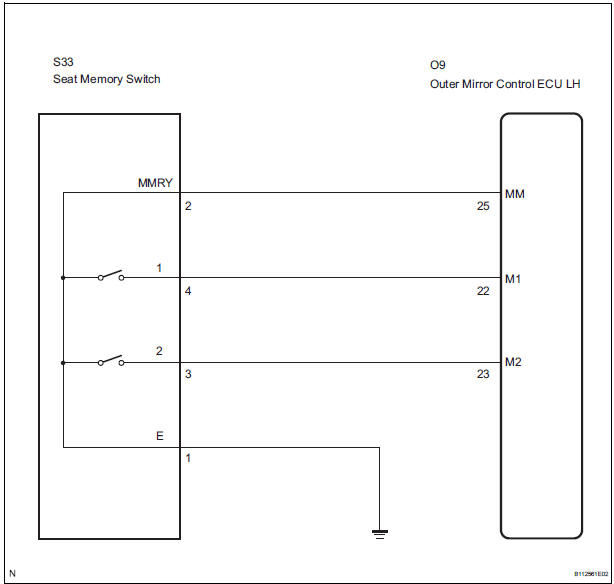
When the seat memory switch M1 or M2 is pressed, the position control ECU & switch (Seat ECU) transmits a signal of the memorized mirror position to the outer mirror control ECU. Then, the outer mirror control ECU drives the mirror motor.
HINT: The power mirror control system is a part of the multiplex communication system. This system features shared communication wiring that reduces the wiring complexity of the communication lines. The first step in any repair is to confirm the proper operation of the communication system. Proceed with troubleshooting after the communication has been verified (See the Multiplex Communication System).
WIRING DIAGRAM
INSPECTION PROCEDURE
1 READ VALUE OF INTELLIGENT TESTER
- Connect the intelligent tester to the DLC3.
- Ignition switch on.
- Enter the following menus: DIAGNOSIS / ENHANCED OBD II / DATA LIST.
- Check the DATA LIST for proper function of the seat memory switch.
D-SEAT
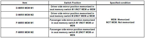
OK: Tester displayed MEM.
2 INSPECT SEAT MEMORY SWITCH
- Remove the seat memory switch.
- Measure the resistance according to the value(s) in the table below when the switch is operated.
Standard resistance

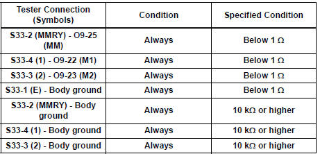
3 CHECK HARNESS AND CONNECTOR (SEAT MEMORY SWITCH - OUTER MIRROR CONTROL ECU)
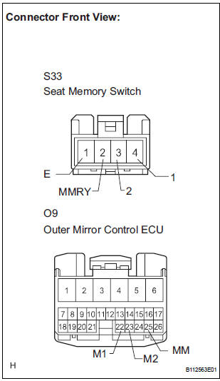
- Disconnect the S33 switch connector.
- Disconnect the O9 ECU connector.
- Measure the resistance according to the value(s) in the table below.
Resistance
REPLACE OUTER MIRROR CONTROL ECU
 Position Sensor Circuit
DESCRIPTION
When SET and 1 or 2 are pressed, the position sensor detects the mirror
position and sends the signal to
the outer mirror control ECU. Then when position 1 or 2 is pressed, the outer
...
 Power Source Circuit
DESCRIPTION
This is the power source circuit for the outer mirror control ECU.
WIRING DIAGRAM
INSPECTION PROCEDURE
1 INSPECT OUTER MIRROR CONTROL ECU (POWER SOURCE)
Disconnect the O9 o ...
Other materials:
Removal
1. DISCONNECT CABLE FROM NEGATIVE BATTERY
TERMINAL
2. DRAIN ENGINE COOLANT
3. REMOVE FRONT WIPER ARM HEAD CAP (See page
WW-4)
4. REMOVE FRONT WIPER ARM RH (See page WW-4)
5. REMOVE FRONT WIPER ARM LH (See page WW-4)
6. REMOVE COWL TOP VENTILATOR LOUVER SUBASSEMBLY
(See page WW-4)
7. REMOVE ...
Setting up intuitive parking assist
You can change the buzzer sound volume and the screen operating
conditions.
Press the “APPS” button.
Select “Setup” on the screen.
Select “Vehicle” on the screen.
Select “TOYOTA Park Assist Settings” on the screen.
Select the desired item.
The buzzer sound volu ...
Transmission Fluid Temperature Sensor "A"
DESCRIPTION
The ATF (Automatic Transmission Fluid) temperature sensor converts the fluid
temperature into a
resistance value which is input into the ECM.
The ECM applies a voltage to the temperature sensor through ECM terminal THO1.
The sensor resistance changes with the transmission f ...
