Toyota Sienna Service Manual: Meter Illumination does not Dim at Night
DESCRIPTION
- Confirm that the vehicle is equipped with the optitron meter, then check this circuit.
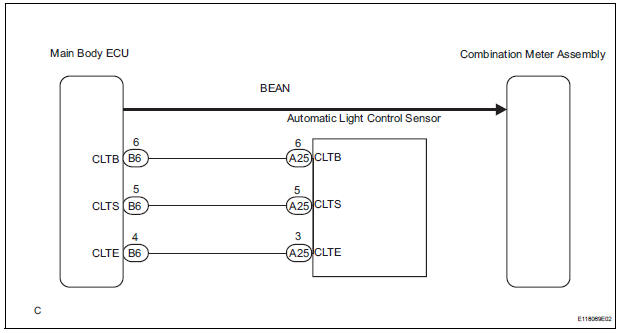
- The combination meter assembly receives a auto dimmer signal from the body ECU by the multiplex communication line.
WIRING DIAGRAM
INSPECTION PROCEDURE
1 CHECK MULTIPLEX COMMUNICATION SYSTEM
- Check if MULTIPLEX communication DTC is output
Result

2 CHECK DTC
- Check if the DTC B1244 is output
Result

3 PERFORM ACTIVE TEST BY INTELLIGENT TESTER
- Operate the intelligent tester according to the steps on the display and select "DATA LIST".
MAIN BODY

OK: The meter illumination is dimmed when the DIMMER SIG is ON.
CHECK LIGHTING SETTING
4 REPLACE COMBINATION METER ASSEMBLY
OK: The operation of the combination meter assembly returns to normal.
END
 Meter Illumination is Always Dark
DESCRIPTION
Confirm that the vehicle is equipped with the optitron meter, then
check this circuit.
The combination meter assembly receives a auto dimmer signal from the
body ECU by t ...
 Combination meter
COMPONENTS
...
Other materials:
Inspection
1. INSPECT CAMSHAFT TIMING OIL CONTROL VALVE ASSEMBLY
Resistance inspection
Using an ohmmeter, measure the resistance
between the terminals.
Resistance:
6.9 to 7.9 Ω at 20C (68F)
If necessary, replace the camshaft timing oil
control valve assembly.
&nbs ...
Installation
1. INSTALL REAR NO. 2 SEAT ASSEMBLY RH
Place the rear No. 2 seat assembly RH in the cabin.
NOTICE:
Be careful not to damage the body.
Install the seat with the bolt.
Torque: 29 N*m (296 kgf*cm, 21 ft.*lbf)
Install the locus cable RH with the bolt.
Torque: 29 N*m ( ...
Update contacts from phone
Operation methods differ between PBAP compatible and PBAP
incompatible but OPP compatible Bluetooth® phones.
If your cellular phone is neither PBAP nor OPP compatible, the contacts
cannot be transferred.
For PBAP Compatible Bluetooth® Phones
Select ÔÇťUpdate Contacts from PhoneÔÇŁ.
Che ...
