Toyota Sienna Service Manual: MIL Circuit
DESCRIPTION
The MIL (Malfunction Indicator Lamp) is used to indicate vehicle malfunctions detected by the ECM.
When the ignition switch is turned to the ON position, power is supplied to the MIL circuit, and the ECM provides the circuit ground which illuminates the MIL.
The MIL operation can be checked visually. When the ignition switch is first turned to the ON position, the MIL should be illuminated and should then turn off. If the MIL remains illuminated or is not illuminated, conduct the following troubleshooting procedure using the intelligent tester.
WIRING DIAGRAM
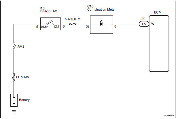
INSPECTION PROCEDURE
1 CHECK THAT MIL IS ILLUMINATED
- Turn the ignition switch to the ON position.
- Check the illumination of the MIL.
Result
2 CHECK WHETHER MIL TURNS OFF
- Connect the intelligent tester to the DLC3.
- Turn the ignition switch to the ON position and turn the tester on.
- Select the following menu items: DIAGNOSIS / ENHANCED OBD II / DTC INFO / CURRENT CODES.
- Check if any DTCs have been stored. Note down any DTCs.
- Clear the DTCs.
- Check if the MIL goes off.
Standard: MIL goes off.
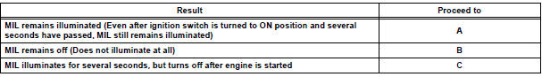
3 CHECK HARNESS AND CONNECTOR (CHECK FOR SHORT IN WIRE HARNESS)
- Disconnect the E5 ECM connector.
- Turn the ignition switch to the ON position.
- Check that the MIL is not illuminated.
OK: MIL is not illuminated.
- Reconnect the ECM connector.
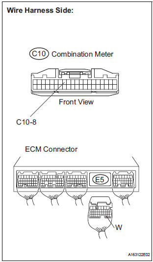
4 CHECK HARNESS AND CONNECTOR (COMBINATION METER - ECM)
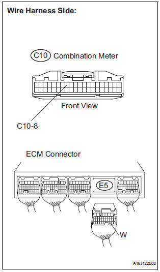
- Disconnect the E5 ECM connector.
- Disconnect the C10 combination meter connector.
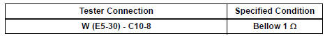
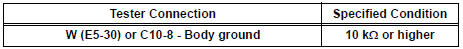
- Measure the resistance according to the value(s) in the table below.
Standard resistance (Check for Open)
Standard resistance (Check for Short)
- Reconnect the ECM connector.
- Reconnect the combination meter connector.
REPAIR OR REPLACE HARNESS OR CONNECTOR (COMBINATION METER - ECM)
5 CHECK THAT ENGINE STARTS
- Turn the ignition switch to the ON position.
- Start the engine.
Result
HINT: *: The intelligent tester cannot communicate with the ECM.
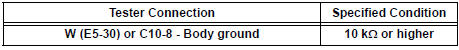
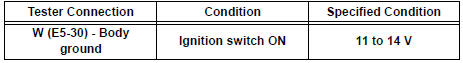
6 CHECK HARNESS AND CONNECTOR (COMBINATION METER - BODY GROUND)
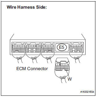
- Disconnect the E5 ECM connector.
- Turn the ignition switch to the ON position.
- Measure the voltage according to the value(s) in the table below.
Standard voltage
- Reconnect the ECM connector.
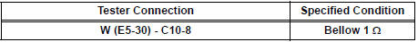
7 CHECK HARNESS AND CONNECTOR (COMBINATION METER - ECM)
- Disconnect the E5 ECM connector.
- Disconnect the C10 combination meter connector.
- Measure the resistance according to the value(s) in the table below.
Standard resistance (Check for short)
Standard resistance (Check for Short)
- Reconnect the ECM connector.
- Reconnect the combination meter connector.
REPLACE COMBINATION METER ASSEMBLY
 Air Intake Control Circuit
DESCRIPTION
The air cleaner is equipped with two inlets, one of which is opened or closed
by the Air Intake Control
Valve (AICV). This system reduces intake noise and increases engine power at
l ...

Other materials:
Third outside seats
To use
Pull the head restraints up.
To fold
Press the button
Removing the head restraints
Front and second outside seats
Pull the head restraint up while pressing
the lock release button.
Second center* and third center seats
Pull the head restraint up while pressi ...
Fuel pump shut off
system
To minimize the risk of fuel leakage when the engine stalls or
when an airbag inflates upon collision, the fuel pump shut off
system stops the supply of fuel to the engine.
Follow the procedure below to restart the engine after the system is
activated.
Vehicles without a smart key system
...
No Signal from Transmitter ID1
DESCRIPTION
The tire pressure warning valve and transmitters that are installed in the
tire and wheel assemblies
measure the air pressure of the tires. The measured values are transmitted to
the tire pressure warning
antenna and receiver on the body as radio waves and then sent to the tir ...
