Toyota Sienna Service Manual: MPX Body ECU Stop
DTC B1200 MPX Body ECU Stop
DESCRIPTION
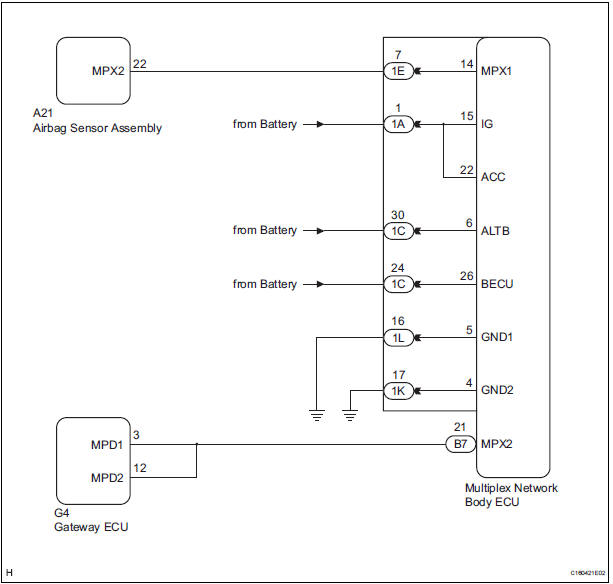
This DTC is detected when communication between the multiplex network body ECU and the multiplex network gateway ECU stops for more than 10 seconds.
|
DTC No. |
DTC Detection Condition |
Trouble Area |
|
B1200 |
Body ECU communication stops |
|
WIRING DIAGRAM
INSPECTION PROCEDURE
1 CHECK HARNESS AND CONNECTOR (MULTIPLEX NETWORK BODY ECU - BATTERY)
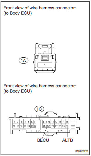
- Disconnect the 1A and 1C junction block connectors.
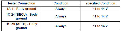
- Measure the voltage according to the value(s) in the table below.
Standard voltage
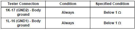
2 CHECK HARNESS AND CONNECTOR (MULTIPLEX NETWORK BODY ECU - GROUND)
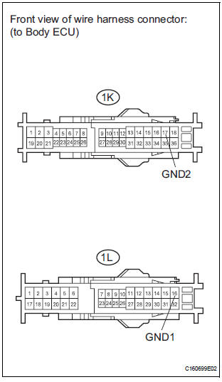
- Disconnect the 1K and 1L junction connectors.
- Measure the resistance according to the value(s) in the table below.
Standard resistance
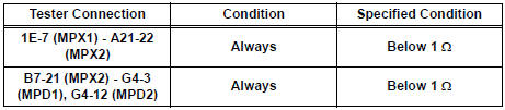
3 CHECK COMMUNICATION LINE
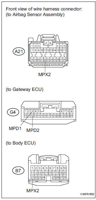
- Disconnect the A21, G4 and B7 ECU connectors.
- Measure the resistance according to the value(s) in the table below.
Standard resistance
Result
REPLACE MULTIPLEX NETWORK BODY ECU
 Diagnostic trouble code chart
If a malfunction code is displayed during the DTC check,
check the circuit listed for that code in the chart below
(Proceed to the page given for that circuit).
MULTIPLEX COMMUNICATION SYSTEM
...
 Passenger Side Outer Mirror ECU
DTC B1208 Passenger Side Outer Mirror ECU
DESCRIPTION
This DTC is detected when communication between the outer mirror control ECU
RH and multiplex
network gateway ECU stops for more than 10 seco ...
Other materials:
Changing the engine switch positions
“LOCK”
The steering wheel is locked and
the key can be removed. (The key
can be removed only when the
shift lever is in “P”.)
“ACC”
Some electrical components such
as the audio system can be used.
“ON”
All electrical components can be
used.
“START”
...
Display
When the sensors detect an obstacle, the following displays inform
the driver of the position and distance to the obstacle.
Multi-information display
Front corner sensor operation
Rear corner sensor operation
Rear center sensor operation
Audio system screen
Intuitive parking ...
Disassembly
1. REMOVE FRONT DISC BRAKE BUSH DUST BOOT
(a) Using soft jaws on the vise, hold the front disc brake
cylinder mounting LH in the vise through aluminum
plates.
(b) Using a screwdriver and hammer, remove the 2
front disc brake bush dust boots from the front disc
brake cylinder mounting LH. ...
