Toyota Sienna Service Manual: Mute Signal Circuit between Radio and Navigation Assembly and Television Display Assembly
DESCRIPTION
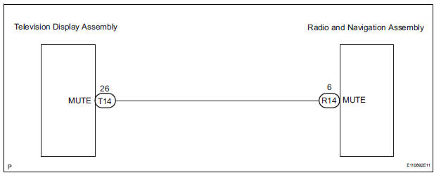
The radio and navigation assembly controls the volume according to the MUTE signal from the television display assembly.
The MUTE signal is sent to reduce noise and a popping sound generated when switching the mode, etc.
If there is an open in the circuit, noise can be heard from the speakers when changing the sound source.
If there is a short in the circuit, even though the radio and navigation assembly is normal, no sound or only an extremely small sound can be produced.
WIRING DIAGRAM
INSPECTION PROCEDURE
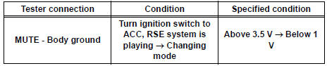
1 INSPECT TELEVISION DISPLAY ASSEMBLY
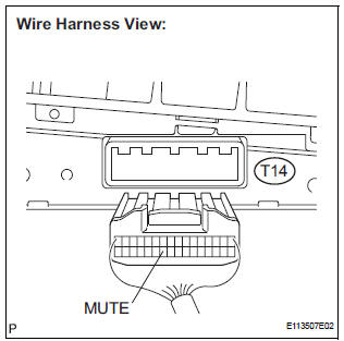
- Measure the voltage according to the value(s) in the table below.
Standard voltage
2 CHECK HARNESS AND CONNECTOR (RADIO AND NAVIGATION ASSEMBLY - TELEVISION DISPLAY ASSEMBLY)
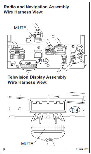
- Disconnect the radio and navigation assembly R14 connector and television display assembly T14 connector.
- Measure the resistance according to the value(s) in the table below.
Standard resistance

3 REPLACE TELEVISION DISPLAY ASSEMBLY
- Replace the television display assembly and check if it operates normally.
OK: The navigation system operates normally.
REPLACE RADIO AND NAVIGATION ASSEMBLY
 Sound Signal Circuit between Radio and Navigation Assembly and
Stereo Jack Adapter
Sound Signal Circuit between Radio and Navigation Assembly and
Stereo Jack Adapter
DESCRIPTION
The stereo jack adapter sends an external device sound signal to the radio
and navigation assembly
through this circuit.
The sound signal that has been sent is amplified by the ster ...
 Mute Signal Circuit between Radio and Navigation Assembly and
Stereo Component Amplifier
Mute Signal Circuit between Radio and Navigation Assembly and
Stereo Component Amplifier
DESCRIPTION
This circuit sends a signal to the stereo component amplifier to mute noise.
Because of that, the noise
produced by changing the sound source ceases.
If there is an open in the circ ...
Other materials:
Types of child restraints
Child restraint systems are classified into the following 3 types
according to the age and size of the child:
Rear facing - Infant seat/convertible seat
Forward facing - Convertible seat
Booster seat
Selecting an appropriate child restraint system
Use a child rest ...
Bluetooth® Audio
Listening to Bluetooth® Audio
The Bluetooth® audio system enables the user to enjoy music
played on a portable player from the vehicle speakers via wireless
communication.
When a Bluetooth® device cannot be connected, check the connection
status on the “Bluetooth* Audio” screen. If the ...
How to proceed with
troubleshooting
HINT:
*: Use the intelligent tester.
1 VEHICLE BROUGHT TO WORKSHOP
2 CUSTOMER PROBLEM ANALYSIS
(a) Confirm problem symptoms
3 CHECK MULTIPLEX COMMUNICATION SYSTEM*
Check if the multiplex communication system DTC is output.
HINT:
The center airbag sensor assembly of this system ...
