Toyota Sienna Service Manual: Mute Signal Circuit between Radio Receiver and Television Display Assembly
DESCRIPTION
The radio receiver controls the volume according to the MUTE signal from the television display assembly.
The MUTE signal is sent to reduce noise and a popping sound generated when switching the mode, etc.
If there is an open in the circuit, noise can be heard from the speakers when changing the sound source.
If there is a short in the circuit, even though the radio receiver is normal, no sound or, only an extremely small sound, can be produced.
WIRING DIAGRAM
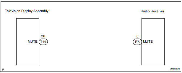
INSPECTION PROCEDURE
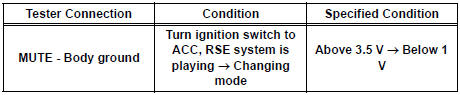
1 INSPECT TELEVISION DISPLAY ASSEMBLY

- Measure the voltage according to the value(s) in the table below.
Standard voltage
2 CHECK HARNESS AND CONNECTOR (RADIO RECEIVER - TELEVISION DISPLAY)
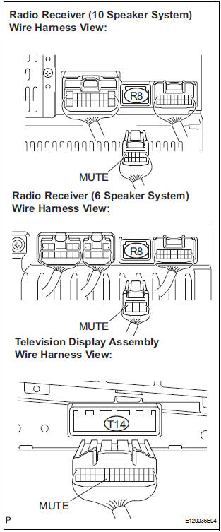
- Disconnect the radio receiver connector R8 and television display assembly connector T14.
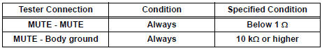
- Measure the resistance according to the value(s) in the table below.
Standard resistance
3 REPLACE TELEVISION DISPLAY ASSEMBLY
- Replace the television display assembly and check if the audio system operates normally.
OK: The audio system operates normally
REPLACE RADIO RECEIVER
 Mute Signal Circuit between Radio Receiver and Stereo Component
Amplifier
Mute Signal Circuit between Radio Receiver and Stereo Component
Amplifier
DESCRIPTION
This circuit sends a signal to the stereo component amplifier to mute noise.
Because of that, the noise
produced by changing the sound source ceases.
If there is an open in the circ ...
 AVC-LAN Circuit
DESCRIPTION
Each unit of the audio system connected to the AVC-LAN (communication bus)
transfers the signal of
each switch by communication.
When a short to +B or short to ground occurs in this ...
Other materials:
Bulb locations
Front
Vehicles without daytime running lights or with bulb type daytime
running lights
Headlight high beam and daytime
running lights (if equipped)
Headlight low beam
(halogen bulb)
Fog light (if equipped)
Front turn signal/parking and
front side marker lights
Vehic ...
License plate light assembly
COMPONENTS
REMOVAL
1. REMOVE BACK DOOR GARNISH CENTER
2. REMOVE BACK DOOR SIDE GARNISH LH
3. REMOVE BACK DOOR SIDE GARNISH RH
4. REMOVE BACK DOOR STRAP COVER
5. REMOVE BACK DOOR PULL STRAP
6. REMOVE BACK DOOR TRIM BOARD ASSEMBLY
7. REMOVE BACK DOOR GARNISH SUB-ASSEMBLY OUTSIDE
8. RE ...
Vehicle Speed Sensor Malfunction
DTC P0500 Vehicle Speed Sensor Malfunction
DTC P0503 Vehicle Speed Sensor "A" Intermittent / Erratic /
High
DESCRIPTION
The cruise control system uses the same vehicle speed signal that is sent to the
ECM for the SFI system.
If DTC P0500 is detected, perform the diagnosis using th ...
