Toyota Sienna Service Manual: Navigation Voice Circuit
DESCRIPTION
This circuit is used when the voice guidance in the navigation system is on.
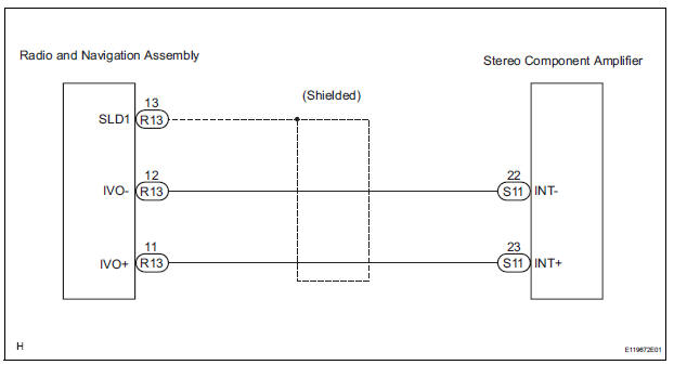
WIRING DIAGRAM
INSPECTION PROCEDURE
1 CHECK HARNESS AND CONNECTOR (RADIO AND NAVIGATION ASSEMBLY - STEREO COMPONENT AMPLIFIER)
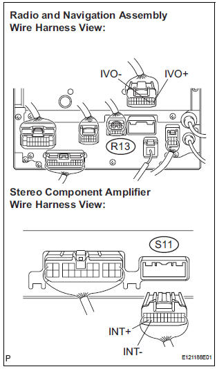
- Disconnect the radio and navigation assembly connector R13 and stereo component amplifier connector S11.
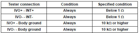
- Measure the resistance according to the value(s) in the table below.
Standard resistance
PROCEED TO NEXT CIRCUIT INSPECTION SHOWN IN PROBLEM SYMPTOMS TABLE
 Reverse Signal Circuit
DESCRIPTION
The radio and navigation assembly receives a reverse signal from the
park/neutral position switch and
information about the GPS antenna, and then adjusts vehicle position.
WIRING DIAG ...
 Display Signal Circuit between Television Display Assembly and Radio
and Navigation Assembly
Display Signal Circuit between Television Display Assembly and Radio
and Navigation Assembly
DESCRIPTION
This circuit sends a DVD image signal from the television display assembly to
the radio and navigation
assembly.
WIRING DIAGRAM
INSPECTION PROCEDURE
1 CHECK HARNESS AND CONNECTO ...
Other materials:
Installation
HINT:
Install the RH side by the same procedure as the LH side.
1. INSTALL REAR SPEED SENSOR
(a) Clean the contacting surface of the axle hub and a
new skid control sensor.
NOTICE:
Keep the sensor rotor clean.
(b) Place the speed sensor on the axle hub so that the
connector is positioned ...
Transponder Chip Malfunction
DTC B2793 Transponder Chip Malfunction
DESCRIPTION
This DTC is output when a malfunction is found in the key during the key code
registration or the key code
is not registered normally. Replace the key when the key code registration is
not performed normally and
this DTC is detected.
IN ...
How to proceed with
troubleshooting
HINT:
The intelligent tester can be used in steps 2, 3, 4, 6 and 9.
1 VEHICLE BROUGHT TO WORKSHOP
2 CONNECT INTELLIGENT TESTER TO DLC3
HINT:
If the display indicates a communication fault in the tester,
inspect the DLC3.
3 CHECK DTC AND FREEZE FRAME DATA
Check for DTC(s) and freeze frame ...
