
Toyota Sienna Service Manual: No. 1 Speaker with box
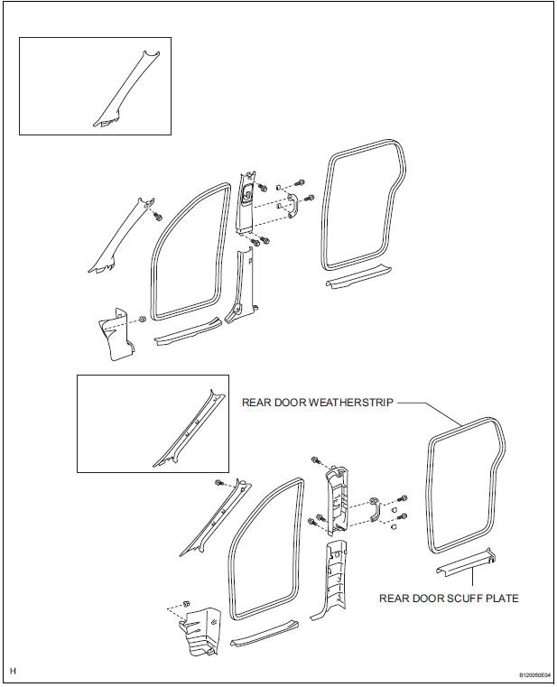
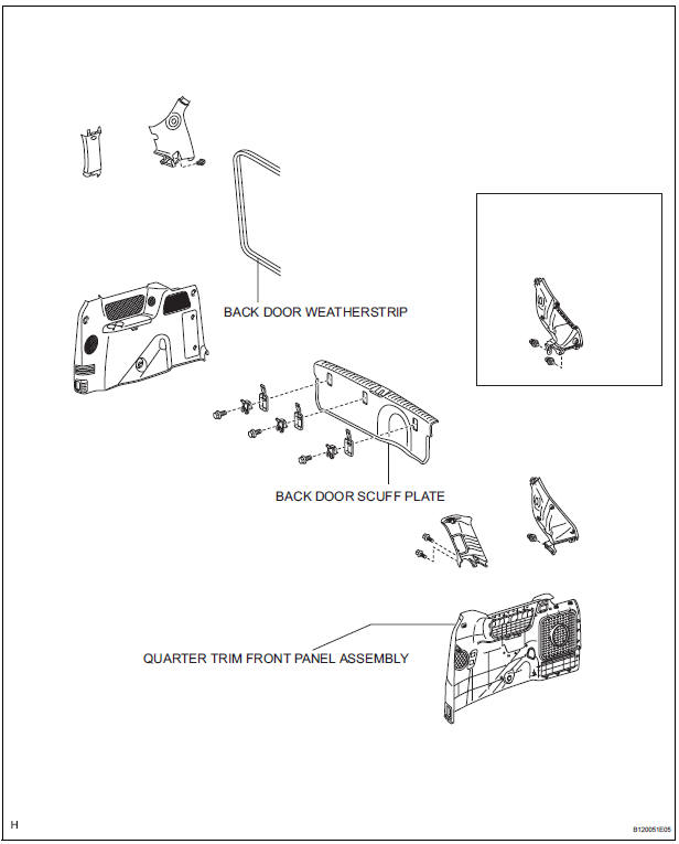
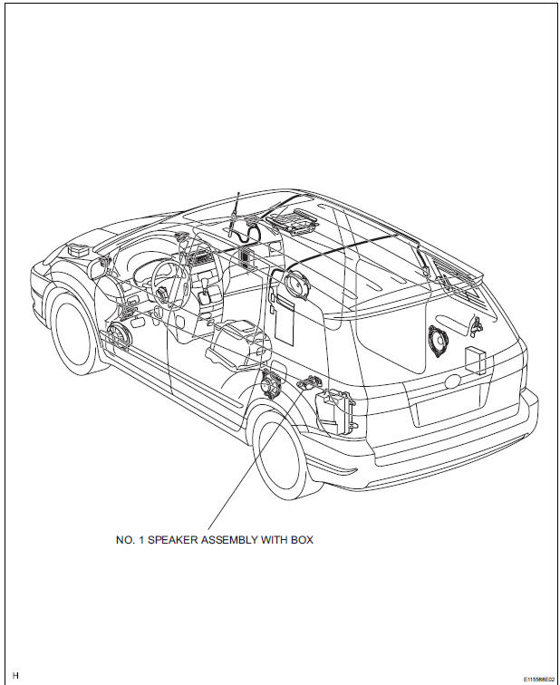
COMPONENTS
ON-VEHICLE INSPECTION
1. INSPECT NO.1 SPEAKER WITH BOX
HINT: Remove interior parts so that the No.1 speaker with box can be seen.
- Check the speaker installation.
OK: The speaker is securely installed.
If the result is not as specified, reinstall the No.1 speaker with box.
- Visually check the speaker.
OK: The cone paper of the speaker is not torn.
If the result is not as specified, replace the No.1 speaker with box.
REMOVAL
1. REMOVE REAR DOOR SCUFF PLATE
2. REMOVE REAR DOOR WEATHERSTRIP
3. REMOVE BACK DOOR WEATHERSTRIP
4. REMOVE BACK DOOR SCUFF PLATE
5. REMOVE QUARTER TRIM FRONT PANEL ASSEMBLY
6. REMOVE NO. 1 SPEAKER ASSEMBLY WITH BOX

- Remove the 2 screws and No. 1 speaker assembly with box.
INSTALLATION
1. INSTALL NO. 1 SPEAKER ASSEMBLY WITH BOX
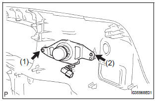
- Install the No. 1 speaker assembly with box with the 2 screws.
NOTICE: Tighten the screws in order shown in the illustration to install the No. 1 speaker assembly with box.
2. INSTALL QUARTER TRIM FRONT PANEL ASSEMBLY
3. INSTALL BACK DOOR SCUFF PLATE
4. INSTALL BACK DOOR WEATHERSTRIP
5. INSTALL REAR DOOR WEATHERSTRIP
6. INSTALL REAR DOOR SCUFF PLATE
 Rear speaker
COMPONENTS
ON-VEHICLE INSPECTION
1. INSPECT REAR SPEAKER
HINT:
Remove interior parts so that the rear speaker can be
seen.
Check the speaker installation.
OK:
The speaker is ...
 No. 2 Speaker with box
COMPONENTS
ON-VEHICLE INSPECTION
1. INSPECT NO.2 SPEAKER WITH BOX
HINT:
Remove interior parts so that the No.2 speaker with box
can be seen.
Check the speaker installation.
OK ...
Other materials:
Operation flow
HINT:
Perform troubleshooting in accordance with the
procedures below. The following is an outline of basic
troubleshooting procedures. Confirm the troubleshooting
procedures for the circuit you are working on before
beginning troubleshooting.
VEHICLE BROUGHT TO WORKSHOP
CUSTOMER PR ...
Installation
1. INSTALL FRONT SUSPENSION ARM SUBASSEMBLY LOWER NO.1 LH
(a) Install the front lower arm bush stopper to the front
suspension arm sub-assembly lower No.1 LH.
(b) Install the bolt and nut to the rear side of the front
suspension arm sub-assembly lower No.1 LH.
Torque: 206 N*m (2,100 kgf ...
Navigation Voice Circuit
DESCRIPTION
This circuit is used when the voice guidance in the navigation system is on.
WIRING DIAGRAM
INSPECTION PROCEDURE
1 CHECK HARNESS AND CONNECTOR (RADIO AND NAVIGATION ASSEMBLY - STEREO
COMPONENT AMPLIFIER)
Disconnect the radio and navigation assembly connector
R13 and s ...
