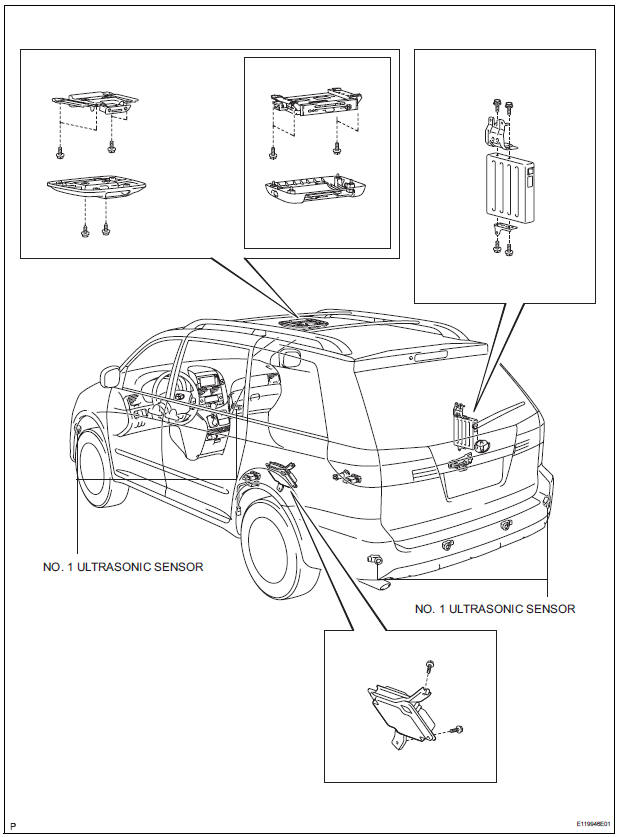
Toyota Sienna Service Manual: No. 1 Ultrasonic sensor
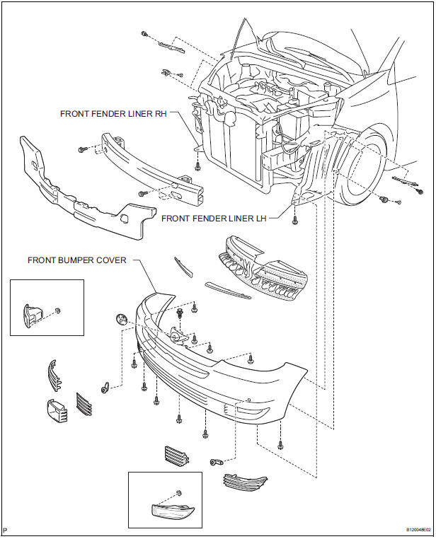
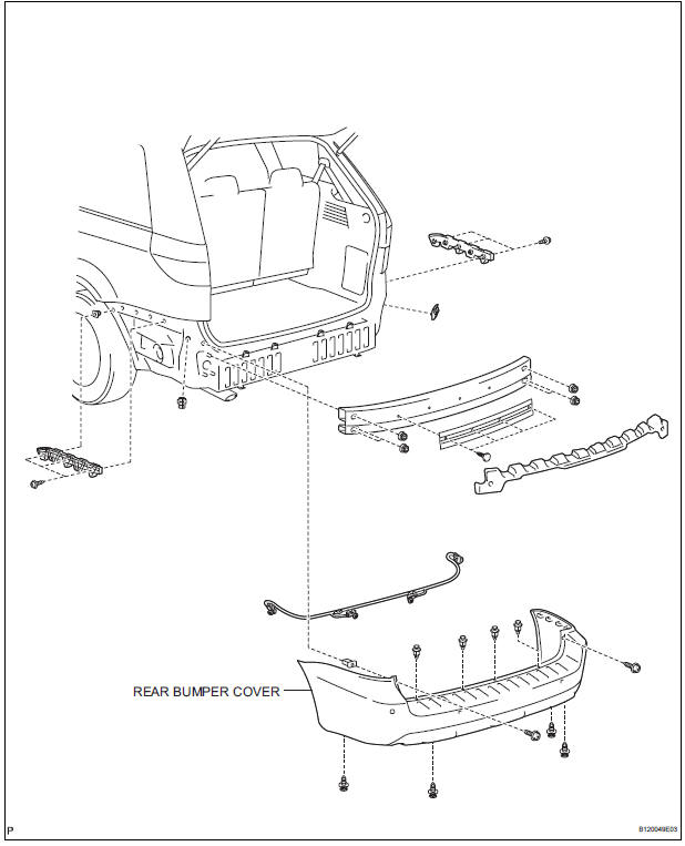
COMPONENTS
REMOVAL
1. REMOVE FRONT FENDER LINER LH
2. REMOVE FRONT FENDER LINER RH
3. REMOVE FRONT BUMPER COVER
4. REMOVE REAR BUMPER COVER (2)
5. REMOVE NO. 1 ULTRASONIC SENSOR RETAINER
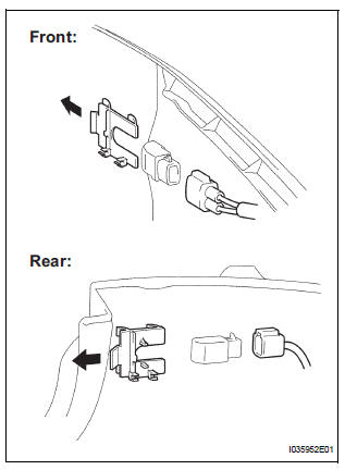
- Remove the No. 1 ultrasonic sensor retainer as shown in the illustration
6. REMOVE NO. 1 ULTRASONIC SENSOR
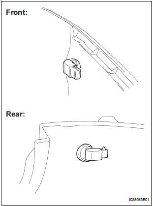
- Disconnect the connector and remove the No. 1 ultrasonic sensor.
INSPECTION
1. INSPECT NO.1 ULTRASONIC SENSOR
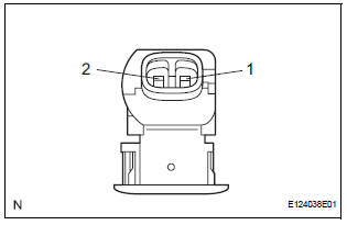
- Measure the resistance according to the value(s) in the table below.
Standard resistance
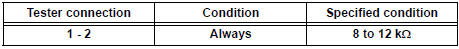
If the result is not as specified, replace No.1 ultrasonic sensor
INSTALLATION
1. INSTALL NO. 1 ULTRASONIC SENSOR
- Connect the connector and install the No. 1 ultrasonic sensor.
2. INSTALL NO. 1 ULTRASONIC SENSOR RETAINER
- Install the No. 1 ultrasonic sensor retainer.
3. INSTALL REAR BUMPER COVER (3)
4. INSTALL FRONT BUMPER COVER
5. INSTALL FRONT FENDER LINER LH
6. INSTALL FRONT FENDER LINER RH
 Clearance warning ECU
COMPONENTS
REMOVAL
1. REMOVE FRONT DOOR SCUFF PLATE LH
2. REMOVE COWL SIDE TRIM BOARD LH
3. REMOVE INSTRUMENT PANEL FINISH PANEL SUBASSEMBLY LOWER LH
4. REMOVE NO. 1 INSTRUMENT PANEL SAFETY PAD ...
 No. 2 Ultrasonic sensor
COMPONENTS
REMOVAL
1. REMOVE REAR BUMPER COVER (2)
2. REMOVE NO. 1 ULTRASONIC SENSOR RETAINER
Remove the No. 1 ultrasonic sensor retainer as
shown in the illustration
3. REMO ...
Other materials:
Precaution
Keep in mind the following points when inspecting the
dynamic laser cruise control system.
As there is a limitation on the vehicle-to-vehicle distance
controlling capability, do not overly rely on the dynamic
laser cruise control system.
Do not neglect to pay constant attentio ...
Sound Signal Circuit between Radio and Navigation Assembly and
Stereo Jack Adapter
DESCRIPTION
The stereo jack adapter sends an external device sound signal to the radio
and navigation assembly
through this circuit.
The sound signal that has been sent is amplified by the stereo component
amplifier and then is sent to the
speakers.
If there is an open or short in the c ...
Disassembly
1. REMOVE AIR REFINER ELEMENT
(a) Release the 2 claw fittings and remove the air filter
sub-assembly.
(b) Remove the air refiner element from the air filter
cover plate.
2. REMOVE COOLING UNIT DAMPER SERVO SUBASSEMBLY
(a) Remove the 3 screws and the cooling unit damper
servo sub-a ...
