Toyota Sienna Service Manual: No. 2 Clearance Warning Buzzer Circuit
DESCRIPTION
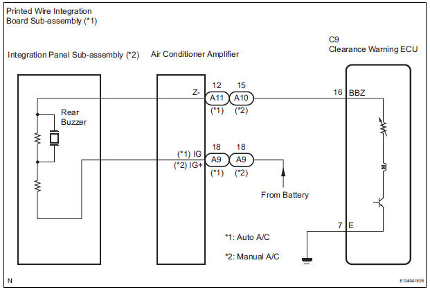
The clearance warning ECU receives the ultrasonic sensor signal to sound the rear warning buzzer.
WIRING DIAGRAM
INSPECTION PROCEDURE
1 CHECK HARNESS AND CONNECTOR (CLEARANCE WARNING ECU - AIR CONDITIONER AMPLIFIER)
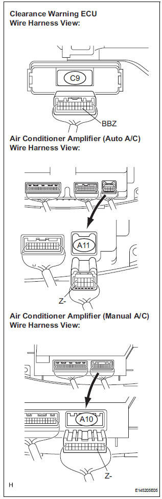
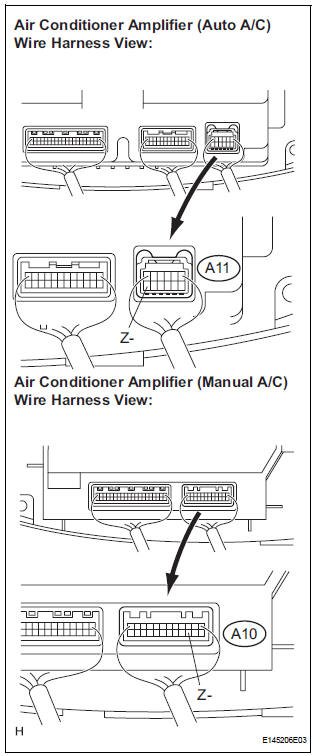
- Disconnect the connectors from the clearance warning ECU C9 and air conditioner amplifier connector A10 or A11.
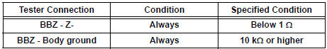
- Measure the resistance according to the value(s) in the table below.
Standard resistance
2 INSPECT REAR BUZZER
- Remove the integration control & panel assembly with the connectors still connected.
- Using a service wire, ground the terminal Z- of the integration control & panel assembly connector.
- Turn the ignition switch ON.
- Check that the rear buzzer sounds.
HINT: The clearance warning buzzer is separately excited, and will not sound unless an alternating voltage is applied.
OK: Operating noise (clicking sounds) can be heard.
Result
PROCEED TO NEXT CIRCUIT INSPECTION SHOWN IN PROBLEM SYMPTOMS TABLE
3 INSPECT PRINTED WIRE INTEGRATION BOARD SUB-ASSEMBLY
- Check that the malfunction disappears when a known good printed wire integration board sub-assembly is installed.
OK: Malfunction disappears.
REPLACE PRINTED WIRE INTEGRATION BOARD SUB-ASSEMBLY
4 INSPECT INTEGRATION PANEL SUB-ASSEMBLY
- Check that the malfunction disappears when a known good integration panel sub-assembly is installed.
OK: Malfunction disappears
REPLACE INTEGRATION PANEL SUB-ASSEMBLY
 Clearance Warning ECU Power Source Circuit
DESCRIPTION
This circuit provides power to the clearance warning ECU.
WIRING DIAGRAM
INSPECTION PROCEDURE
1 CHECK HARNESS AND CONNECTOR (CLEARANCE WARNING ECU - AIR CONDITIONER
AMPLIFIER)
...
 Indicator Circuit
DESCRIPTION
The indicator displays the location of the obstacle and the approximate
distance between the vehicle and
the obstacle either by blinking or turning on.
WIRING DIAGRAM
INSPECTION ...
Other materials:
Disassembly
1. Remove repair service starter kit
(a) Remove the nut and disconnect the lead wire from
the repair service starter kit.
(b) Remove the 2 screws which are used to secure the
repair service starter kit to the repair service starter
kit.
(c) Remove the repair service starter kit.
( ...
Precaution
1. REMOVAL AND INSTALLATION TIRE PRESSURE
WARNING VALVE AND TRANSMITTER
(a) When installing a tire, make sure that the tire
pressure warning valve and transmitter does not
interfere with the tire bead in order to prevent
damage to the tire pressure warning valve and
transmitter.
(b) After c ...
Gyro Error
DTC 58-10 Gyro Error
DTC 80-10 Gyro Error
DESCRIPTION
DTC No.
DTC Detection Condition
Trouble Area
58-10
Ground short, power supply short, or open circuit in the
gyro signal
Gyro sensor
Radio and navigation assembly
80-10
...
