Toyota Sienna Service Manual: No Answer-Back (Hazard Warning Light and Wireless Door Lock Buzzer)
DESCRIPTION If there is no answer-back of the hazard light signal and the wireless door lock buzzer although the wireless control function is operating normally, there might be a malfunction in the hazard light signal and the wireless door lock buzzer signal which are output from the multiplex network body ECU.
NOTICE: Troubleshooting should be started after confirming that the answer-back function has been switched ON through customization.
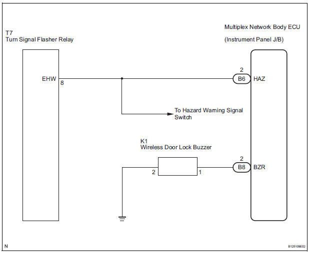
WIRING DIAGRAM
INSPECTION PROCEDURE
When using intelligent tester:
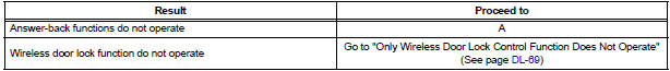
1 CHECK WIRELESS DOOR LOCK CONTROL SYSTEM
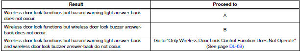
- Check whether the wireless door lock functions by operating the transmitter switch.
HINT: When the wireless door LOCK/UNLOCK operation can be performed, it means that the wireless signal from the transmitter is properly input to the multiplex network body ECU
Result
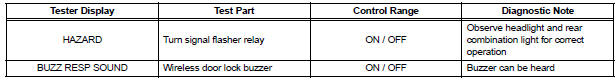
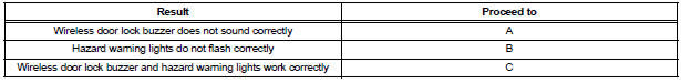
2 PERFORM ACTIVE TEST BY INTELLIGENT TESTER
- Connect the intelligent tester to the DLC3.
- Turn the ignition switch ON and push the intelligent tester main switch ON.
- Select the item "HAZARD" in the ACTIVE TEST and check the turn signal flasher relay ON/OFF.
- Select the item "BUZZ RESP SOUND" in the ACTIVE TEST and check the wireless buzzer ON/OFF
BODY:
Result
3 CHECK HAZARD WARNING LIGHTS
- Check that the hazard warning lights blink when the hazard warning signal switch is pressed.
REPLACE MULTIPLEX NETWORK BODY ECU
4 INSPECT WIRELESS DOOR LOCK BUZZER

- Check the buzzer resistance.
NOTICE:
- The buzzer circuit is built into the ECU, not into the buzzer itself.
- When battery voltage is directly applied to the buzzer, the buzzer does not sound.
- Check the resistance between terminals of the buzzer.
Standard
5 CHECK HARNESS AND CONNECTOR (WIRELESS DOOR LOCK BUZZER - MULTIPLEX NETWORK BODY ECU)
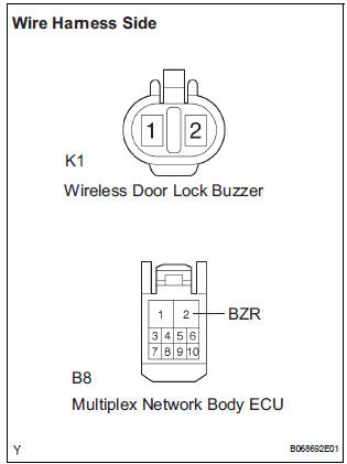
- Disconnect the K1 buzzer connector and B8 ECU connector.
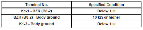
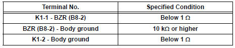
- Measure the resistance according to the value(s) in the table below.
Standard resistance
REPLACE MULTIPLEX NETWORK BODY ECU
When not using intelligent tester:
1 CHECK WIRELESS DOOR LOCK CONTROL SYSTEM
- Check whether the wireless door lock functions by operating the transmitter switch.
HINT: When the wireless door LOCK/UNLOCK operation can be performed, it means that the wireless signal from the transmitter is properly input to the multiplex network body ECU
Result
2 CHECK HAZARD WARNING LIGHTS
- Check that the hazard warning lights blink when the hazard warning signal switch is pressed.
REPLACE MULTIPLEX NETWORK BODY ECU
3 INSPECT WIRELESS DOOR LOCK BUZZER
- Check the buzzer resistance.
NOTICE:
- The buzzer circuit is built into the body ECU, not into the buzzer itself.
- When battery voltage is directly applied to the buzzer, the buzzer does not sound.
- Check the resistance between terminals of the buzzer.
Standard resistance
4 CHECK HARNESS AND CONNECTOR (WIRELESS DOOR LOCK BUZZER - MULTIPLEX NETWORK BODY ECU)
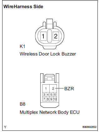
- Disconnect the K1 wireless buzzer connector and B8 ECU connector.
- Measure the resistance according to the value(s) in the table below.
Standard resistance
REPLACE MULTIPLEX NETWORK BODY ECU
 Wireless Door Lock Tuner Circuit Malfunction
DTC B1242 Wireless Door Lock Tuner Circuit Malfunction
DESCRIPTION
When a RDA signal is not input to the door control receiver within 1 second
after the multiplex network
body ECU outputs a PRG s ...
 Only Wireless Door Lock Control Function does not Operate
DESCRIPTION
The door control receiver receives a signal from the transmitter and sends
this signal to the multiplex
network body ECU. Then, the multiplex network body ECU controls operation of the ...
Other materials:
No Communication in Immobiliser System
DTC B2796 No Communication in Immobiliser System
DTC B2798 Communication Malfunction No. 2
DESCRIPTION
These codes are stored in the memory when a key that does not have a
transponder chip is inserted or if
communication between the key and transponder key ECU is impossible.
DTC No ...
All Doors cannot be Locked / Unlocked at Once
DESCRIPTION
The body ECU receives a switch signal from the master switch, the door
control switch, the driver door
key cylinder and the passenger door key cylinder and then drives the door lock
motor.
WIRING DIAGRAM
INSPECTION PROCEDURE
1 INSPECT FUSE (ECU-B)
Remove ECU-B fuse f ...
Short in Driver Side Squib Circuit
DTC B0100/13 Short in Driver Side Squib Circuit
DESCRIPTION
The driver side squib circuit consists of the center airbag sensor assembly,
the spiral cable and the
steering pad. The circuit instructs the SRS to deploy when deployment conditions
are met. DTC B0100/13
is recorded when a short ci ...
