Toyota Sienna Service Manual: No Master/ Connection Check Error
DTC 01-D6 No Master
DTC 01-D7 Connection Check Error
DESCRIPTION
|
DTC No. |
DTC Detection Condition |
Trouble Area |
| 01-D6 *1 | When either of the following conditions is met:
|
|
| 01-D7 *2 | When either of the following conditions is met:
|
HINT:
- *1: Even if no fault is present, this trouble code may be stored depending on the battery condition or engine start voltage.
- *2: When 210 seconds have elapsed after disconnecting the power supply connector of the master component with the ignition switch is in the ACC or ON position, this code is stored.
NOTICE:
- Before starting troubleshooting, be sure to clear DTCs to erase codes stored due to the reasons described in the HINT above. Then, check for DTCs and troubleshoot according to the output DTCs.
- The radio and navigation assembly is the master unit.
- Be sure to clear and recheck DTCs after the inspection is completed to confirm that no DTCs are output.
INSPECTION PROCEDURE
NOTICE: Be sure to read DESCRIPTION before performing the following procedures.
1 CHECK RADIO AND NAVIGATION ASSEMBLY POWER SOURCE CIRCUIT
Refer to the radio and navigation assembly power source circuit.
If the power source circuit is operating normally, proceed to the next step
2 IDENTIFY THE COMPONENT WHICH HAS STORED THIS CODE
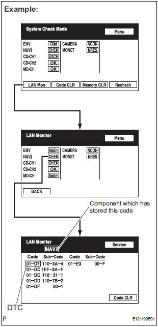
- Enter the diagnostic mode.
- Press the "LAN Mon" switch to change to "LAN Monitor" mode.
- Identify the component which has stored this code.
Component Table:
HINT: "NAVI" is the component which has stored this code in the example shown in the illustration
3 CHECK POWER SOURCE CIRCUIT OF COMPONENT WHICH HAS STORED THIS CODE
- Inspect the power source circuit of the component which
has stored this code.
If the power source circuit is operating normally, proceed to the next step
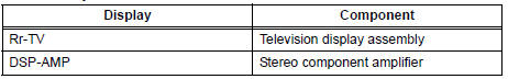
Component Table:
|
Component |
Proceed to |
| Television display assembly (Rr-TV) | Television display assembly power source circuit |
| Stereo component amplifier (DSP-AMP) | Stereo component amplifier power source circuit |
4 CHECK RADIO AND NAVIGATION ASSEMBLY
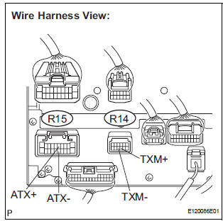
- Disconnect the radio and navigation assembly connectors.
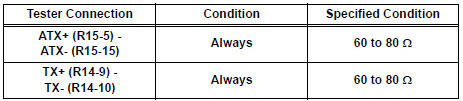
- Measure the resistance according to the value(s) in the table below.
Standard resistance
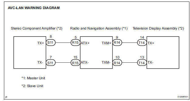
5 CHECK HARNESS AND CONNECTOR
HINT: For details of the connectors, refer to "TERMINALS OF ECU".
- Referring to the AVC-LAN wiring diagram below, check the AVC-LAN circuit between the radio and navigation assembly and the component which has stored this code.
- Disconnect all connectors between the radio and navigation assembly and the component which has stored this code.
- Check for an open or short in the AVC-LAN circuit between the radio and navigation assembly and the component which has stored this code.
OK: There is no open or short circuit.
6 REPLACE COMPONENT WHICH HAS STORED THIS CODE
- Replace the component which has stored this code with a normal one and check if the same problem occurs again.
OK: Same problem does not occur.
END
 Absence of Registration Unit/ No Response for Connection Check/ Last Mode
Error/ No Response Against ON / OFF Command/ Mode Status Error/ Slave Reset
Absence of Registration Unit/ No Response for Connection Check/ Last Mode
Error/ No Response Against ON / OFF Command/ Mode Status Error/ Slave Reset
DTC 01-D5 Absence of Registration Unit
DTC 01-D8 No Response for Connection Check
DTC 01-D9 Last Mode Error
DTC 01-DA No Response Against ON / OFF Command
DTC 01-DB Mode Status Error
DTC 01-DE Sl ...
 Transmission Error
DTC 01-DC Transmission Error
DESCRIPTION
DTC No.
DTC Detection Condition
Trouble Area
01-DC
*1
Transmission to component shown by sub-code failed.
(Detec ...
Other materials:
Center Airbag Sensor Assembly Malfunction
DTC B1100/31 Center Airbag Sensor Assembly Malfunction
DESCRIPTION
The center airbag sensor assembly consists of the center airbag sensor
assembly, safing sensor, drive
circuit, diagnosis circuit and ignition control, etc.
It receives signals from the airbag sensor, judges whether or not the ...
Removal
1. DISCONNECT CABLE FROM NEGATIVE BATTERY
TERMINAL
2. REMOVE AIR FUEL RATIO SENSOR (for Bank 2
Sensor 1)
(a) Disconnect the sensor connector.
(b) Using SST, remove the sensor from the exhaust
manifold.
SST 09224-00010
3. REMOVE FRONT EXHAUST PIPE ASSEMBLY
(a) Disconnect the heat ...
Stowing the flat tire
Take out the strap and tire bag.
Place tire standing up in rear
tub, after putting the tire in the
tire bag.
Clip clasp to outboard hook.
Clip other clasp to center or
opposite hook location.
Pull strap to tighten and secure
tire.
...
