Toyota Sienna Service Manual: On-vehicle inspection
1. INSPECT BRAKE PEDAL HEIGHT
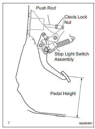
(a) Check the brake pedal height.
Pedal height from dash panel: 150.3 to 160.3 mm (5.917 to 6.311 in.)
NOTICE: Do not adjust the pedal height. Doing so by changing the push rod length will structurally change the pedal ratio.
2. CHECK AND ADJUST STOP LIGHT SWITCH
(a) Disconnect the stop light switch assembly connector from the stop light switch assembly.
(b) Turn the stop light switch assembly counterclockwise and remove the stop light switch assembly.
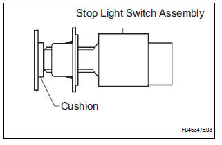
(c) Insert the stop light switch assembly until the body hits the cushion.
NOTICE: When inserting the stop light switch assembly, support the pedal from behind so that the pedal is not pushed in.
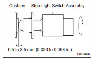
(d) Make a quarter turn clockwise to install the stop light switch assembly.
NOTICE:
- When inserting the stop light switch assembly, support the pedal from behind so that the pedal is not pushed in.
- The turning torque for installing the stop light switch assembly
Torque: 1.5 N*m (15 kgf*cm, 13 in.*lbf) or less
(e) Connect the stop light switch connector to the stop light switch assembly.
(f) Check the protrusion of the rod.
Protrusion of the rod: 0.5 to 2.5mm (0.020 to 0.098 in.)
3. CHECK PEDAL FREE PLAY
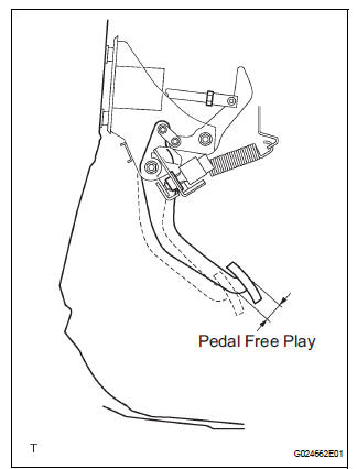
(a) Stop the engine and depress the brake pedal several times until there is no more vacuum left in the booster.
(b) Push in the pedal until the beginning of the resistance is felt. Measure the distance, as shown.
Pedal free play: 1 to 6 mm (0.04 to 0.24 in.)
4. CHECK PEDAL RESERVE DISTANCE
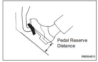
(a) Release the parking brake pedal.
With the engine running, depress the pedal and measure the pedal reserve distance, as shown.
Pedal reserve distance from asphalt sheet at 490 N (50 kgf, 110 lbf): More than 52 mm (2.0 in.)
HINT: If the distance is out of the specification, troubleshoot the brake system.
 Brake pedal
Components
...
 Removal
1. SEPARATE BATTERY NEGATIVE TERMINAL
2. REMOVE FRONT DOOR SCUFF PLATE LH
3. REMOVE COWL SIDE TRIM BOARD LH
4. REMOVE INSTRUMENT PANEL FINISH PANEL SUBASSEMBLY
LOWER LH
(a) Remove the 2 bolts and ...
Other materials:
Installation
1. Install air fuel ratio sensor (for bank 2
sensor 1)
(a) Using SST, install the sensor to the exhaust
manifold LH.
SST 09224-00010
Torque: 40 N*m (408 kgf*cm, 30 ft.*lbf) for use
with SST
44 N*m (449 kgf*cm, 32 ft.*lbf) for use
without SST
HINT:
Use a torque wrench with a fulcrum ...
System description
1. OUTLINE
As a unique feature of Rear Seat Entertainment
(RSE) system, the front and rear seat occupants can
enjoy different audio-visual modes at the same time.
Thus, this system offers enhanced entertainment to
the rear seat occupants.
The rear seat occupants can control the ...
Using a flatbed truck
If you use chains or cables to tie
down your vehicle, the angles
shaded in black must be 45.
Do not overly tighten the tie
downs or the vehicle may be damaged.
WARNINGObserve the following precautions.
Failure to do so may result in death or serious injury.
When tow ...
