Toyota Sienna Service Manual: On-vehicle inspection
1. INSPECT BRAKE BOOSTER
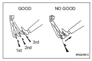
(a) Air tightness check.
(1) Start the engine and stop it after 1 or 2 minutes.
Depress the brake pedal several times slowly.
HINT: If the pedal goes down farthest at the 1st time, and gradually rises at the 2nd or 3rd time, the booster is airtight.
(2) Depress the brake pedal while the engine is running, and stop the engine with the pedal depressed.
HINT: If there is no change in the pedal reserve distance after holding the pedal for 30 seconds, the booster is airtight.
(b) Operating check.
(1) Depress the brake pedal several times with the ignition switch OFF and check that there is no change in the pedal reserve distance.
(2) Depress the brake pedal and start the engine.
HINT: If the pedal goes down slightly, the operation is normal.
 Brake booster
COMPONENTS
...
 Removal
NOTICE:
Do not adjust the brake booster push rod.
Do not change the combination of the diameter
converting unit and brake.
1. REMOVE FRONT WHEEL
2. DRAIN BRAKE FLUID
NOTICE:
Wash the bra ...
Other materials:
Data list / active test
1. DATA LIST
HINT:
With the intelligent tester connected to the DLC3 and the
ignition switch to the ON position, the ABS, TRAC and
VSC data list can be displayed. Follow the prompts on
the tester screen to access the DATA LIST.
*: 2WD
2. ACTIVE TEST
HINT:
Performing the ACTIVE TEST usin ...
When servicing full-time 4wd vehicles
The full-time 4WD SIENNA is equipped with the open
center differential system.
If incorrect preparations or test procedures are used, the
test will not only be unsuccessful, but may be dangerous
as well.
Therefore, before beginning any such servicing or test,
be sure to check the following ...
Installation
HINT:
Use the same procedures for the RH side and LH side.
The procedures listed below are for the LH side.
1. INSTALL CURTAIN SHIELD AIRBAG ASSEMBLY LH
Install the curtain shield airbag assembly LH with
the 13 bolts in the order shown in the illustration.
Torque: 14 N*m ...
