Toyota Sienna Service Manual: On-vehicle inspection
1. INSPECT THROTTLE BODY
(a) Listen to the throttle control motor operating sounds.
(1) Turn the ignition switch to the ON position.
(2) When pressing the accelerator pedal position sensor lever, listen to the running motor. Make sure that no friction noise comes from the motor.
If friction noise exists, replace the throttle body.
(b) Inspect the throttle position sensor.
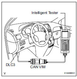
(1) Connect the intelligent tester to the DLC3.
(2) Turn the ignition switch to the ON position.
(3) Check that the MIL turns off.
(4) Under CURRENT DATA, the throttle valve opening percentage (THROTTLE POS) should be within the standard range below.
Standard throttle valve opening percentage: 60% or more If the percentage is less than 60%, replace the throttle body.
| NOTICE: When checking the throttle valve opening percentage, the transmission should be in neutral. |
 Throttle body
COMPONENTS
...
 Removal
1. Remove windshield wiper motor assembly
hint:
(see page ww-4)
2. Remove front outer cowl top panel subassembly
(see page em-27)
3. Drain engine coolant (see page co-6)
4. Remove v-bank cover s ...
Other materials:
Registration
NOTICE:
The Vehicle Identification Number (VIN) must be input
into the replacement ECM.
HINT:
The VIN is a 17-digit alphanumeric vehicle identification
number. The intelligent tester is required to register the VIN.
1. INPUT INSTRUCTIONS
The general VIN input instructions using the
...
Removal
HINT:
Replace the RH side by the same procedures as the LH side.
1. REMOVE REAR WHEEL
2. REMOVE REAR AXLE SHAFT LH NUT (See page DS-
22)
3. SEPARATE REAR DISC BRAKE CALIPER
ASSEMBLY LH
(a) Removing the 2 bolts, separate the rear disc brake
caliper assembly LH.
4. REMOVE REAR DISC
5. SEPARA ...
Installation
1. INSTALL TIRE PRESSURE WARNING ECU
(a) Connect the connector to the tire pressure warning
ECU.
(b) Install the tire pressure warning ECU with the screw.
2. INSTALL INSTRUMENT PANEL SAFETY PAD SUBASSEMBLY
HINT:
Refer to the instructions for INSTALLATION of the
instrument panel safety ...
