Toyota Sienna Service Manual: On-vehicle inspection
1. INSPECT FUEL CUT RPM
(a) Increase the engine speed to at least 3500 rpm.
(b) Use a sound scope to check for injector operating sounds.
(c) Check that when the throttle lever is released, injector operating sounds stop momentarily (at 2500 rpm) and then resume (at 1400 rpm).
Standard 
2. CHECK AIR TIGHTNESS IN FUEL TANK AND FILLER PIPE
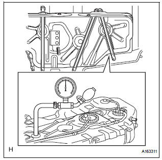
(a) Disconnect the vent line hose from the fuel tank.
(b) Connect the pressure gauge to the fuel tank.
(c) Apply pressure to the fuel tank to create an internal pressure of 4 kPa (41 gf/cm2, 0.58 psi).
(d) Check that the internal pressure of the fuel tank is maintained for 1 minute.
(e) Check the connected portions of each hose and pipe.
(f) Check the installed parts on the fuel tank.
If any malfunctions, damage or other problems are found, replace the fuel tank and filler pipe.
(g) Reconnect the vent line hose to the fuel tank.
3. INSPECT FUEL CUT OFF VALVE AND FUEL CHECK VALVE
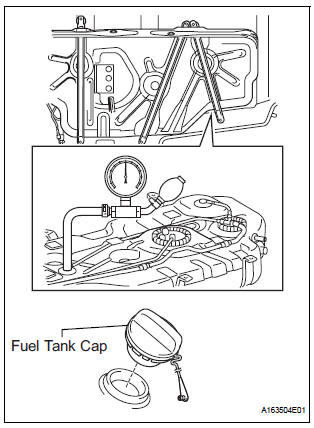
(a) Disconnect the vent line hose from the fuel tank.
(b) Connect the pressure gauge to the fuel tank.
(c) Fill the fuel tank with fuel.
(d) Apply pressure of 4 kPa (41 gf/cm2, 0.58 psi) to the vent port of the fuel tank.
HINT: Check the amount of fuel in the fuel tank. When the fuel tank is full, the float valve of the fill check valve is closed and no air can pass through.
(e) Remove the fuel tank cap, and check that the pressure drops.
If the pressure does not drop, replace the fuel tank assembly.
(f) Reconnect the vent line hose to the fuel tank.
4. CHECK AIR INLET LINE
(a) Disconnect the air inlet line hose from the charcoal canister.
(b) Check that air can flow freely into the air inlet line.
If air cannot flow freely into the air inlet line, repair or replace it.
(c) Reconnect the air inlet line hose to the charcoal canister.
5. VISUALLY INSPECT HOSES, CONNECTORS AND GASKETS
(a) Check for cracks, leaks or damage.
HINT:
Removal or problems with the engine oil dipstick, oil filler cap, PCV hose and other components may cause the engine to run improperly. Disconnection, looseness or cracks in the parts of the air induction system between the throttle body and cylinder head will allow air suction and cause the engine to run improperly.
If necessary, replace any damaged parts.
 Parts location
System diagram
...
 Canister
Components
...
Other materials:
Installation
1. INSTALL STEERING COLUMN ASSEMBLY
(a) Install the steering column assembly with the 3
bolts.
Torque: 25 N*m (255 kgf*cm, 18 ft.*lbf)
(b) Connect the connectors.
(c) Connect the wire harness clamps to the steering
column tube.
2. CONNECT STEERING INTERMEDIATE SHAFT ASSEMBLY
(a) ...
DTC check / clear
1. CHECK DTC (USING INTELLIGENT TESTER)
Checking DTCs.
Connect the intelligent tester to the DLC3.
Turn the ignition switch ON.
Read DTCs by following the prompts on the
tester screen.
HINT:
Refer to the intelligent tester operator's manual
for further deta ...
Pressure Control Solenoid "B" Electrical (Shift
Solenoid Valve SL2)
DESCRIPTION
Shifting from 1st to 5th is performed in combination with "ON" and "OFF"
operation of the shift solenoid
valves SL1, SL2, SL3, S4 and SR which are controlled by the ECM. If an open or
short circuit occurs in
either of the shift solenoid valves, the ECM cont ...
