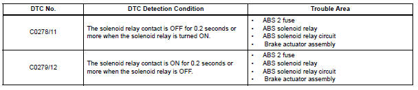
Toyota Sienna Service Manual: Open in ABS Solenoid Relay Circuit
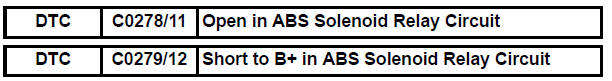
DESCRIPTION
This relay supplies power to each ABS solenoid.
Immediately after the ignition switch is turned to the ON position, the relay turns on if the solenoid is determined to be normal as a result of self-diagnosis during initial check.
The relay turns off if an open/short is detected.
If the voltage supplied to the motor relay (+BS) is below the DTC detection threshold due to low voltage from the battery/alternator, the DTCs may be stored.
WIRING DIAGRAM
Refer to DTCs C0226/21, C0236/22, C0246/23 and C0256/24 (See page BC-29).
INSPECTION PROCEDURE
1 INSPECT FUSE (ABS 2 FUSE)
(a) Remove the ABS 2 fuse from the FL block.
(b) Measure the resistance according to the value(s) in the table below.
Standard resistance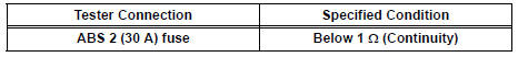


2 INSPECT SKID CONTROL ECU (+BS TERMINAL VOLTAGE)
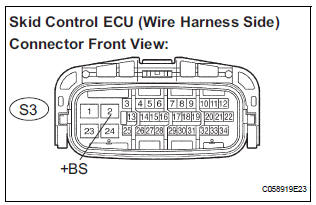
(a) Install the ABS 2 fuse.
(b) Disconnect the skid control ECU connector.
(c) Measure the voltage according to the value(s) in the table below
Standard voltage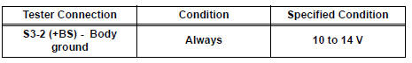

3 INSPECT SKID CONTROL ECU (GND TERMINAL CONTINUITY)
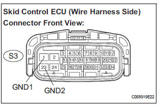
(a) Measure the resistance according to the value(s) in the table below.
Standard resistance 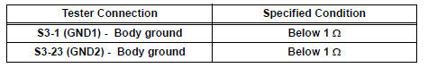

4 RECONFIRM DTC
(a) Clear the DTCs (See page BC-10).
(b) Start the engine.
(c) Drive the vehicle at the speed of 6 km/h (4 mph) or more.
(d) Check that the same DTCs are recorded (See page BC- 10).
HINT:
- Reinstall the sensors, connectors, etc. and restore the vehicle to its prior condition before rechecking for DTCs.
- If a speed signal of 6 km/h (4 mph) or more is input to the skid control ECU, with the ignition switch on and the stop light switch off, the ECU performs selfdiagnosis of the motor and solenoid circuits.
Result
HINT:
- If any DTCs are output while jiggling a connector or wire harness of the brake actuator (skid control ECU), inspect and repair the connector or wire harness.
- If the normal system code is output, slightly jiggle the connectors, wire harnesses, and fuses of the brake actuator assembly. Make sure that no DTCs are output.
- These DTCs may be memorized due to a malfunction in the connector terminal connection, etc.

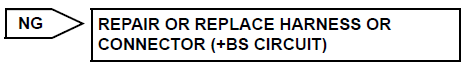
REPLACE BRAKE ACTUATOR ASSEMBLY
 Open in ABS Motor Relay Circuit
DESCRIPTION
The ABS motor relay supplies power to the ABS pump motor. While the ABS is
activated, the ECU turns
the motor relay on and operates the ABS pump motor.
If the voltage supplied t ...
 Low Battery Positive Voltage
DTC C1241/41 Low Battery Positive Voltage
DESCRIPTION
If there is a problem with the brake actuator assembly (skid control ECU)
power supply circuit, the skid
control ECU outputs the DTC and proh ...
Other materials:
Inspection
1. INSPECT FRONT STABILIZER LINK ASSEMBLY LH
(a) As shown in the illustration, flip the ball joint stud
back and forth 5 times, before installing the nut.
(b) Using a torque wrench, turn the nut continuously at
a rate of 2 to 4 seconds per 1 turn and take the
torque reading on the 5th turn.
...
Speed sensor check (when using intelligent tester)
(a) Check the backward signal.
(1) Drive the vehicle in reverse for more than 1
second at 3 km/h (2 mph) or higher.
HINT:
Drive the vehicle in reverse and check the speed
sensor signal. Note that the signal check cannot
be completed if the vehicle speed is 45 km/h (28
mph) or more.
(b) Che ...
Driver Side Seat Belt Warning Light does not Operate
DESCRIPTION
When turning the ignition switch to the ON position, the combination meter
assembly communicates with
the supplemental restraint system by the multiplex communication system. Unless
the driver side seat
belt is fastened, the combination meter assembly will turn on the seat belt
...
