Toyota Sienna Service Manual: Open in Curtain Shield Squib RH Circuit
DTC B1161/84 Open in Curtain Shield Squib RH Circuit
DESCRIPTION
The curtain shield squib RH circuit consists of the center airbag sensor assembly and the curtain shield airbag assembly RH.
The circuit instructs the SRS to deploy when deployment conditions are met.
DTC B1161/84 is recorded when an open circuit is detected in the curtain shield squib RH circuit.
|
DTC No. |
DTC Detecting Condition |
Trouble Area |
|
B1161/84 |
|
|
INSPECTION PROCEDURE
HINT:
- Perform the simulation method by selecting the "check mode" (signal check) with the intelligent tester (8).
- After selecting the "check mode" (signal check), perform the simulation method by wiggling each connector of the airbag system or driving the vehicle on a city or rough road
1 CHECK CURTAIN SHIELD AIRBAG ASSEMBLY RH (CURTAIN SHIELD SQUIB RH)
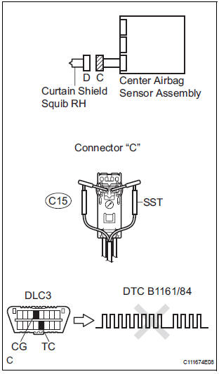
- Turn the ignition switch to the LOCK position.
- Disconnect the negative (-) terminal cable from the battery, and wait for at least 90 seconds.
- Disconnect the connectors from the curtain shield airbag assembly RH.
- Connect the white wire side of SST (resistance 2.1 Ω) to the floor wire No. 2.
CAUTION: Never connect a tester to the curtain shield airbag assembly RH (Curtain shield squib RH) for measurement, as this may lead to a serious injury due to airbag deployment.
NOTICE: Do not forcibly insert the SST into the terminals of the connector when connecting.
Insert the SST straight into the terminals of the connector.
SST 09843-18060
- Connect the negative (-) terminal cable to the battery, and wait for at least 2 seconds.
- Turn the ignition switch to the ON position, and wait for at least 60 seconds.
- Clear the DTCs stored in memory (5).
- Turn the ignition switch to the LOCK position.
- Turn the ignition switch to the ON position, and wait for at least 60 seconds.
- Check the DTCs
OK: DTC B1161/84 is not output.
HINT: Codes other than DTC B1161/84 may be output at this time, but they are not related to this check
 Go to step 2

REPLACE CURTAIN SHIELD AIRBAG ASSEMBLY RH
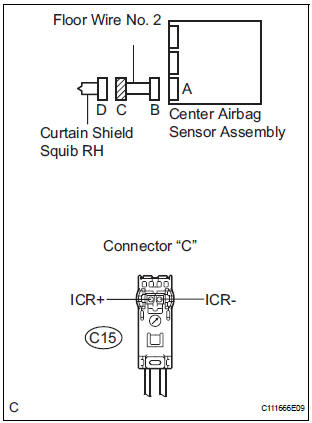
2 CHECK FLOOR WIRE NO.2 (CURTAIN SHIELD SQUIB RH CIRCUIT)
- Turn the ignition switch to the LOCK position.
- Disconnect the negative (-) terminal cable from the battery, and wait for at least 90 seconds.
- Disconnect the SST (resistance 2.1 Ω) from the floor wire No. 2.
- Disconnect the connector from the center airbag sensor assembly.
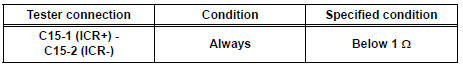
- Measure the resistance according to the value(s) in the table below.
Standard resistance
 REPAIR OR REPLACE FLOOR WIRE
NO.2
REPAIR OR REPLACE FLOOR WIRE
NO.2

3 CHECK CENTER AIRBAG SENSOR ASSEMBLY
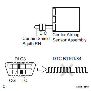
- Connect the connectors to the curtain shield airbag assembly RH and the center airbag sensor assembly.
- Connect the negative (-) terminal cable to the battery, and wait for at least 2 seconds.
- Turn the ignition switch to the ON position, and wait for at least 60 seconds.
- Clear the DTCs stored in memory (5).
- Turn the ignition switch to the LOCK position.
- Turn the ignition switch to the ON position, and wait for at least 60 seconds.
- Check the DTCs (5).
OK: DTC B1161/84 is not output. HINT: Codes other than DTC B1161/84 may be output at this time, but they are not related to this check.
 REPLACE CENTER AIRBAG SENSOR
ASSEMBLY
REPLACE CENTER AIRBAG SENSOR
ASSEMBLY

USE SIMULATION METHOD TO CHECK
 Short in Curtain Shield Squib RH Circuit
DTC B1160/83 Short in Curtain Shield Squib RH Circuit
DESCRIPTION
The curtain shield squib RH circuit consists of the center airbag sensor
assembly and the curtain shield
airbag assembly RH.
T ...
 Short to GND in Curtain Shield Squib RH Circuit
DTC B1162/81 Short to GND in Curtain Shield Squib RH Circuit
DESCRIPTION
The curtain shield squib RH circuit consists of the center airbag sensor
assembly and the curtain shield
airbag assembly R ...
Other materials:
ABS Warning Light does not Come ON
WIRING DIAGRAM
Refer to ABS Warning Light Remains ON (See page BC-141).
INSPECTION PROCEDURE
1 CHECK ABS WARNING LIGHT
(a) Disconnect the skid control ECU connector.
(b) Turn the ignition switch to the ON position.
(c) Check that the ABS warning light comes on.
OK:
ABS warning light come ...
Problem symptoms table
HINT:
Before inspecting the suspected areas listed in the table
below, check the fuse and relay.
Before inspecting the suspected areas listed in the table
below, check the DTCs.
Methods used to verify the cause of the problem are listed
in order of probability in the ...
Disposal
HINT:
When scrapping a vehicle equipped with the SRS or
disposing of the front passenger airbag assembly, be sure to
deploy the airbag first in accordance with the procedure
described below. If any abnormality occurs with airbag
deployment, contact the SERVICE DEPT. of the TOYOTA
MOTOR SALES, ...
