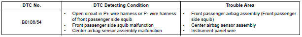
Toyota Sienna Service Manual: Open in Front Passenger Side Squib Circuit
DTC B0106/54 Open in Front Passenger Side Squib Circuit
DESCRIPTION
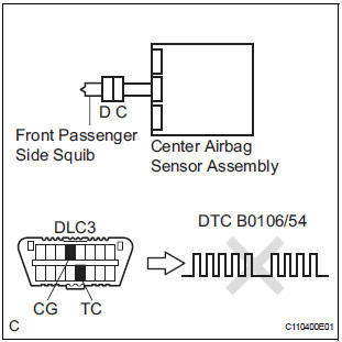
The front passenger side squib circuit consists of the center airbag sensor assembly and the front passenger airbag assembly.
The circuit instructs the SRS to deploy when deployment conditions are met.
DTC B0106/54 is recorded when an open circuit is detected in the front passenger side squib circuit.
WIRING DIAGRAM
INSPECTION PROCEDURE
HINT:
- Perform the simulation method by selecting the "check mode" (signal check) with the intelligent tester.
- After selecting the "check mode" (signal check), perform the simulation method by wiggling each connector of the airbag system or driving the vehicle on a city or rough road
1 CHECK FRONT PASSENGER AIRBAG ASSEMBLY (FRONT PASSENGER SIDE SQUIB)
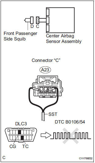
- Turn the ignition switch to the LOCK position.
- Disconnect the negative (-) terminal cable from the battery, and wait for at least 90 seconds.
- Disconnect the connectors from the front passenger airbag assembly.
- Connect the black wire side of SST (resistance 2.1 Ω) to the instrument panel wire.
CAUTION: Never connect a tester to the front passenger airbag assembly (front passenger side squib) for measurement, as this may lead to a serious injury due to airbag deployment.
NOTICE: Do not forcibly insert the SST into the terminals of the connector when connecting.
Insert the SST straight into the terminals of the connector.
SST 09843-18060
- Connect the negative (-) terminal cable to the battery, and wait for at least 2 seconds.
- Turn the ignition switch to the ON position, and wait for at least 60 seconds.
- Clear the DTCs stored in memory.
- Turn the ignition switch to the LOCK position.
- Turn the ignition switch to the ON position, and wait for at least 60 seconds.
- Check the DTCs
OK: DTC B0106/54 is not output.
HINT: Codes other than DTC B0106/54 may be output at this time, but they are not related to this check.
REPLACE FRONT PASSENGER AIRBAG ASSEMBLY
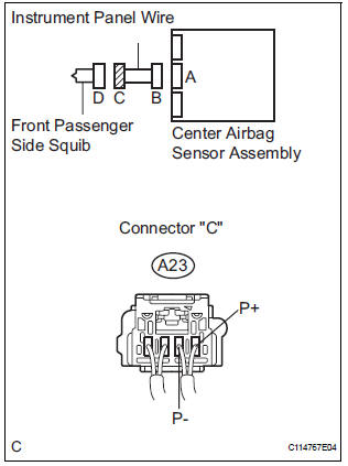
2 CHECK INSTRUMENT PANEL WIRE (FRONT PASSENGER SIDE SQUIB CIRCUIT)
- Turn the ignition switch to the LOCK position.
- Disconnect the negative (-) terminal cable from the battery, and wait for at least 90 seconds.
- Disconnect the SST (resistance 2.1 Ω) from the instrument panel wire.
- Disconnect the connector from the center airbag sensor assembly.
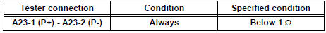
- Measure the resistance according to the value(s) in the table below.
Standard resistance
3 CHECK CENTER AIRBAG SENSOR ASSEMBLY
- Connect the connectors to the front passenger airbag assembly and the center airbag sensor assembly.
- Connect the negative (-) terminal cable to the battery, and wait for at least 2 seconds.
- Turn the ignition switch to the ON position, and wait for at least 60 seconds.
- Clear the DTCs stored in memory.
- Turn the ignition switch to the LOCK position.
- Turn the ignition switch to the ON position, and wait for at least 60 seconds.
- Check the DTCs.
OK: DTC B0106/54 is not output.
HINT: Codes other than code B0106/54 may be output at this time, but they are not related to this check.
USE SIMULATION METHOD TO CHECK
 Short in Front Passenger Side Squib Circuit
DTC B0105/53 Short in Front Passenger Side Squib Circuit
DESCRIPTION
The front passenger side squib circuit consists of the center airbag sensor
assembly and the front
passenger airbag assembly.
...
 Short to GND in Front Passenger Side Squib
Circuit
Short to GND in Front Passenger Side Squib
Circuit
DTC B0107/51 Short to GND in Front Passenger Side Squib
Circuit
DESCRIPTION
The front passenger side squib circuit consists of the center airbag sensor
assembly and the front
passenger airbag as ...
Other materials:
High pitched horn
COMPONENTS
REMOVAL
1. REMOVE FRONT BUMPER COVER
2. REMOVE HIGH PITCHED HORN
Disconnect the connector.
Remove the bolt and horn.
INSPECTION
1. INSPECT HIGH PITCHED HORN
Apply battery voltage and check operation of the
horn, as shown in the table.
Standard ...
Power Slide Door Warning Buzzer RH does not Sound
DESCRIPTION
The power slide door system uses warning buzzers built into RH
slide doors respectively. Each buzzer
has 2 ways of sounding that are used differently according to the
situations:
When all the following conditions are met, the warning buzzer sounds at
a cycle of ...
Terminals of ECU
1. CHECK DISTANCE CONTROL ECU
Reference: waveform 1
HINT:
Terminal: LRDD - SGND
Gauge set: 2 V/DIV., 10 ms./DIV.
Condition: ignition switch in the ON position
Reference: waveform 2
HINT:
Terminal: LRRD - SGND
Gauge set: 2 V/ ...
