Toyota Sienna Service Manual: Open in Occupant Classification ECU Battery Positive Line
DTC B1794 Open in Occupant Classification ECU Battery Positive Line
DESCRIPTION
This circuit consists of the occupant classification ECU and the power source circuit (battery, fuse, wire harness).
DTC B1794 is recorded when a malfunction is detected in the occupant classification ECU or the power source circuit.
HINT: When DTC B1794 is output after switching the ignition switch LOCK-ON-LOCK 50 times in a row when a malfunction occurs in the power circuit for the occupant classification system, the DTC is output again when a malfunction is detected even once after being cleared, unless the normal system code is
|
DTC No. |
DTC Detecting Condition |
Trouble Area |
|
B1794 |
|
|
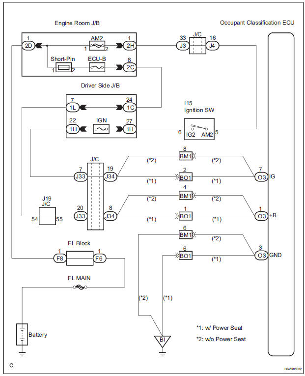
WIRING DIAGRAM
INSPECTION PROCEDURE
1 CHECK BATTERY
- Measure the voltage of the battery.
Standard: 11 to 14 V
2 CHECK FUSE
- Check the ECU-B fuse.
Standard: Below 1 Ω
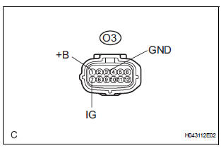
3 CHECK WIRE HARNESS
- Turn the ignition switch to the LOCK position.
- Disconnect the negative (-) terminal cable from the battery, and wait for at least 90 seconds.
- Disconnect the connector from the occupant classification ECU.
- Connect the negative (-) terminal cable to the battery.
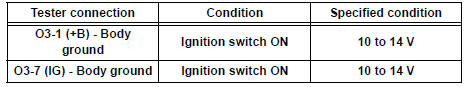
- Turn the ignition switch to the ON position.
- Measure the voltage and resistance according to the value(s) in the table below.
Standard voltage
- Turn the ignition switch to the LOCK position.
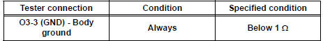
- Measure the resistance and resistance according to the value(s) in the table below.
Standard resistance
4 CHECK DTC
- Turn the ignition switch to the ON position.
(b) Clear the DTCs stored in memory (35).
HINT: First clear DTCs stored in the occupant classification ECU and then in the center airbag sensor assembly.
- Turn the ignition switch to the LOCK position.
- Turn the ignition switch to the ON position, and wait for at least 10 seconds.
- Using the intelligent tester, check the DTCs of the occupant classification ECU (35).
OK: DTC B1794 is not output. HINT: Codes other than code B1794 may be output at this time, but they are not related to this check.
USE SIMULATION METHOD TO CHECK
5 REPLACE OCCUPANT CLASSIFICATION ECU
- Turn the ignition switch to the LOCK position.
- Disconnect the negative (-) terminal cable from the battery, and wait for at least 90 seconds.
- Replace the occupant classification ECU
6 PERFORM ZERO POINT CALIBRATION
- Connect the negative (-) terminal cable to the battery.
- Connect the intelligent tester to the DLC3.
- Turn the ignition switch to the ON position.
- Using the intelligent tester, perform the "Zero point calibration" (28).
OK: The "COMPLETED" is displayed.
7 PERFORM SENSITIVITY CHECK
- Using the intelligent tester, perform the "Sensitivity check"
Standard value: 27 to 33 kg (59.52 to 72.75 lb)
END
 Occupant Classification Sensor Power Supply
Circuit Malfunction
Occupant Classification Sensor Power Supply
Circuit Malfunction
DTC B1793 Occupant Classification Sensor Power Supply
Circuit Malfunction
DESCRIPTION
The occupant classification sensor power supply circuit consists of the
occupant classification ECU and
the ...
 Occupant Classification ECU Malfunction
DTC B1795 Occupant Classification ECU Malfunction
DESCRIPTION
DTC B1795 is recorded when a malfunction is detected in the occupant
classification ECU.
Troubleshoot DTC B1771 first when the DTCs ...
Other materials:
Rear speaker
COMPONENTS
ON-VEHICLE INSPECTION
1. INSPECT REAR SPEAKER
HINT:
Remove interior parts so that the rear speaker can be
seen.
Check the speaker installation.
OK:
The speaker is securely installed.
If the result is not as specified, reinstall the rear
speaker.
Vi ...
Deleting the contact data
For PBAP compatible Bluetooth® phones, this function is available when
“Automatic Transfer” is set to off.
Select “Delete Contacts”.
Select the desired contact and select “Delete”.
Select “Yes” when the confirmation screen appears.
Deleting the contact in a different w ...
Removal
1. REMOVE REAR WHEEL
2. REMOVE SKID CONTROL SENSOR WIRE (for 2WD)
(a) Disconnect the skid control sensor connector.
(b) Remove the bolt and disconnect the bracket from
the rear axle beam assembly.
HINT:
Separate the RH side by the same procedures as
the LH side.
3. SEPARATE SPEED SENSO ...
