Toyota Sienna Service Manual: Open in Pump Motor Circuit
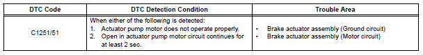
DTC C1251/51 Open in Pump Motor Circuit
DESCRIPTION
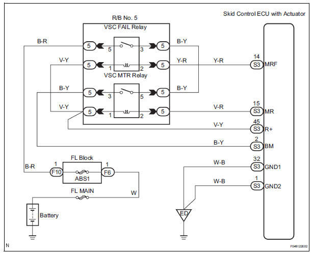
WIRING DIAGRAM
INSPECTION PROCEDURE
1 PERFORM ACTIVE TEST USING INTELLIGENT TESTER (ABS MOTOR RELAY)
(a) Connect the intelligent tester to the DLC3.
(b) Start the engine.
(c) Select the ACTIVE TEST mode on the intelligent tester.
ABS / VSC: 
(d) Check the operation sound of the ABS motor individually when operating it with the intelligent tester.
OK: The operation sound of the ABS motor should be heard.
NOTICE: When replacing the brake actuator assembly, perform zero point calibration (See page BC-70).

REPLACE BRAKE ACTUATOR ASSEMBLY
2 INSPECT SKID CONTROL ECU (GND2 TERMINAL)
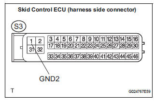
(a) Disconnect the skid control ECU connector.
(b) Measure the resistance according to the value(s) in the table below.
Standard resistance 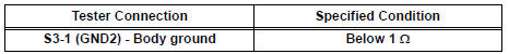
NOTICE: When replacing the brake actuator assembly, perform zero point calibration (See page BC-70).

REPLACE BRAKE ACTUATOR ASSEMBLY
 Open in Stop Light Switch Circuit
DTC C1249/49 Open in Stop Light Switch Circuit
DESCRIPTION
WIRING DIAGRAM
INSPECTION PROCEDURE
1 CHECK STOP LIGHT SWITCH OPERATION
(a) Check that the stop light comes on when the brak ...
 Steering Angle Sensor Zero Point Malfunction
DTC C1290/66 Steering Angle Sensor Zero Point Malfunction
DESCRIPTION
The skid control ECU acquires steering angle sensor zero point every time the
ignition switch is turned to
the ON position an ...
Other materials:
Installation
1. INSTALL REAR NO. 2 SEAT ASSEMBLY LH
Place the rear No. 2 seat assembly LH in the cabin.
NOTICE:
Be careful not to damage the body.
Install the rear No. 2 seat assembly LH with the 2
bolts.
Torque: 29 N*m (296 kgf*cm, 21 ft.*lbf)
Install the locus cable with the ...
Rear Power Seat Switch Circuit
DESCRIPTION
When the power rear no. 2 seat switch is operated, a recline signal is sent
to the fold seat control ECU.
The ECU activates the reclining motor based on the signal from the power rear
no. 2 seat switch.
WIRING DIAGRAM
INSPECTION PROCEDURE
1 INSPECT FOLD SEAT CONTROL ECU
...
Diagnosis system
1. DESCRIPTION
(a) Release the parking brake pedal.
(b) Check the warning lights.
When ignition switch is turned ON, check that the
ABS warning light and brake warning light come on
for 3 seconds.
HINT:
When parking brake is applied or the level of the
brake fluid is low, the bra ...
