Toyota Sienna Service Manual: Open in Side Squib RH Circuit
DTC B0111/44 Open in Side Squib RH Circuit
DESCRIPTION
The side squib RH circuit consists of the center airbag sensor assembly and the front seat side airbag assembly RH.
The circuit instructs the SRS to deploy when deployment conditions are met.
DTC B0111/44 is recorded when an open circuit is detected in the side squib RH circuit.
|
DTC No. |
DTC Detecting Condition |
Trouble Area |
|
B0111/44 |
|
|
INSPECTION PROCEDURE
HINT:
- Perform the simulation method by selecting the "check mode" (signal check) with the intelligent tester (8).
- After selecting the "check mode" (signal check), perform the simulation method by wiggling each connector of the airbag system or driving the vehicle on a city or rough road
1 CHECK FRONT SEAT SIDE AIRBAG ASSEMBLY RH (SIDE SQUIB RH)
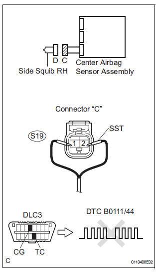
- Turn the ignition switch to the LOCK position.
- Disconnect the negative (-) terminal cable from the battery, and wait for at least 90 seconds.
- Disconnect the connectors from the front seat side airbag assembly RH.
- Connect the black wire side of SST (resistance 2.1 Ω) to the floor wire No. 2.
CAUTION: Never connect a tester to the front seat side airbag assembly RH (side squib RH) for measurement, as this may lead to a serious injury due to airbag deployment.
NOTICE: Do not forcibly insert the SST into the terminals of the connector when connecting.
Insert the SST straight into the terminals of the connector.
SST 09843-18060
- Connect the negative (-) terminal cable to the battery, and wait for at least 2 seconds.
- Turn the ignition switch to the ON position, and wait for at least 60 seconds.
- Clear the DTCs stored in memory (5).
- Turn the ignition switch to the LOCK position.
- Turn the ignition switch to the ON position, and wait for at least 60 seconds.
- Check the DTCs
OK: DTC B0111/44 is not output. HINT: Codes other than DTC B0111/44 may be output at this time, but they are not related to this check.
 Go to step 2

REPLACE FRONT SEAT ASSEMBLY RH
2 CHECK FLOOR WIRE NO.2 (SIDE SQUIB RH CIRCUIT)
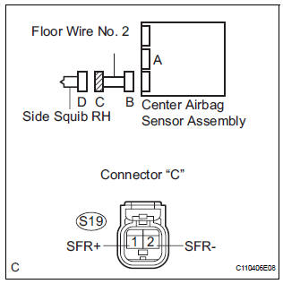
- Turn the ignition switch to the LOCK position.
- Disconnect the negative (-) terminal cable from the battery, and wait for at least 90 seconds.
- Disconnect the SST (resistance 2.1 Ω) from the floor wire No. 2.
- Disconnect the connector from the center airbag sensor assembly.
- Measure the resistance according to the value(s) in the table below.
Standard resistance
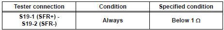
 REPAIR OR REPLACE FLOOR WIRE
NO.2
REPAIR OR REPLACE FLOOR WIRE
NO.2

3 CHECK CENTER AIRBAG SENSOR ASSEMBLY
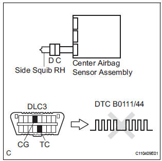
- Connect the connectors to the front seat side airbag assembly RH and the center airbag sensor assembly.
- Connect the negative (-) terminal cable to the battery, and wait for at least 2 seconds.
- Turn the ignition switch to the ON position, and wait for at least 60 seconds.
- Clear the DTCs stored in memory (5).
- Turn the ignition switch to the LOCK position.
- Turn the ignition switch to the ON position, and wait for at least 60 seconds.
- Check the DTCs (5).
OK: DTC B0111/44 is not output. HINT: Codes other than code B0111/44 may be output at this time, but they are not related to this check.
REPLACE CENTER AIRBAG SENSOR
ASSEMBLY
USE SIMULATION METHOD TO CHECK
 Short in Side Squib RH Circuit
DTC B0110/43 Short in Side Squib RH Circuit
DESCRIPTION
The side squib RH circuit consists of the center airbag sensor assembly and
the front seat side airbag
assembly RH.
The circuit instruct ...
 Short to GND in Side Squib RH Circuit
DTC B0112/41 Short to GND in Side Squib RH Circuit
DESCRIPTION
The side squib RH circuit consists of the center airbag sensor assembly and
the front seat side airbag
assembly RH.
The circuit i ...
Other materials:
Turn signal light switch
ON-VEHICLE INSPECTION
1. INSPECT TURN SIGNAL FLASHER CIRCUIT
Measure voltage between the terminals as shown in
the chart below.
Voltage
Connect the connector to turn the signal flasher and
turn the ignition switch ON, and inspect the wire
harness side connector from t ...
Mirror Motor Circuit
DESCRIPTION
A mirror control switch signal and memorized mirror positions are sent to the
outer mirror control ECU.
The outer mirror control ECU drives the selected mirror UP, DOWN, LEFT and RIGHT
in response to the
inputs.
HINT:
The power mirror control system is part of the large-scale ...
Power mirror control system (w/o Memory)
PARTS LOCATION
Problem symptoms table
POWER MIRROR CONTROL SYSTEM
Symptom
Suspected area
Mirror does not operate
Outer mirror switch assembly
Outer rear view mirror assembly
Wire harness
Mirror operates abnormally
O ...
