Toyota Sienna Service Manual: Operating Light Control Rheostat does not Change Light Brightness
DESCRIPTION
The meter CPU receives signals for adjusting illumination on the meter from this circuit. The meter CPU detects the illumination level selected by the user according to the position of the rheostat knob.
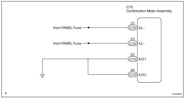
WIRING DIAGRAM
INSPECTION PROCEDURE
1 READ VALUE OF INTELLIGENT TESTER (LIGHT RHEOSTAT)
- Connect the intelligent tester to the DLC3.
- Turn the switch to the ON position.
- Turn the tester ON.
- Enter the following menus: DIAGNOSIS / OBD/MOBD / METER / DATA LIST.
- Check the values by referring to the table below.
METER:
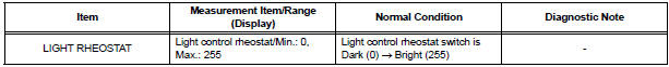
OK: Light brightness displayed on the tester is almost the same as the actual light brightness.
REPLACE COMBINATION METER ASSEMBLY
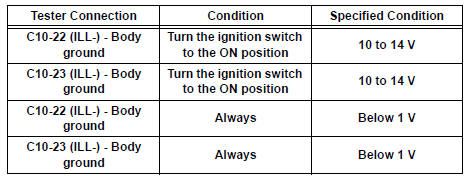
2 CHECK HARNESS AND CONNECTOR (LIGHT CONTROL RHEOSTAT CIRCUIT)
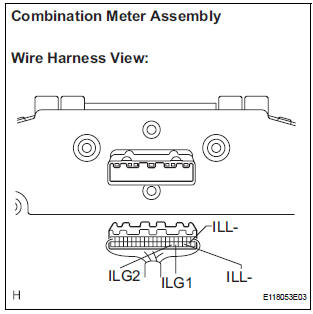
- Disconnect the C10 connectors.
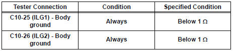
- Measure the resistance according to the value(s) in the table below.
Standard resistance
- Measure the voltage according to the value(s) in the table below.
Standard voltage
REPLACE COMBINATION METER ASSEMBLY
 Driver Side Seat Belt Warning Light does not Operate
DESCRIPTION
When turning the ignition switch to the ON position, the combination meter
assembly communicates with
the supplemental restraint system by the multiplex communication system. Unless
...
 Meter Illumination is Always Dark
DESCRIPTION
Confirm that the vehicle is equipped with the optitron meter, then
check this circuit.
The combination meter assembly receives a auto dimmer signal from the
body ECU by t ...
Other materials:
Reassembly
1. INSTALL FRONT DOOR WIRE LH
Install the wire with the 2 bolts.
Torque: Reference
8.0 N*m (82 kgf*cm, 71 in.*lbf)
NOTICE:
In order to prevent water leakage, be sure that
the lip of the rubber grommet does not turn up
or is not deformed when installing the wire.
Connect the wir ...
Power Slide Door LH does not Operate When Using Inside / Outside
Handle
DESCRIPTION
The inside / outside handles have the ability to control operation
of the power slide door. Pulling either
handle transmits a request signal to the power slide door ECU LH, which then
commands the power
slide door control motor and clutch to open / close the power sli ...
Throttle / Pedal Position Sensor / Switch "D"
Circuit Range / Performance
DTC P2121 Throttle / Pedal Position Sensor / Switch "D"
Circuit Range / Performance
HINT:
This DTC relates to the Accelerator Pedal Position (APP) sensor.
DESCRIPTION
Refer to DTC P2120
MONITOR DESCRIPTION
The accelerator pedal position sensor is mounted on the accelerator pedal ...
