Toyota Sienna 2010-2026 Owners Manual: Operation
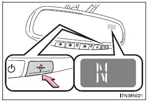
To turn the compass on or off, press the switch.
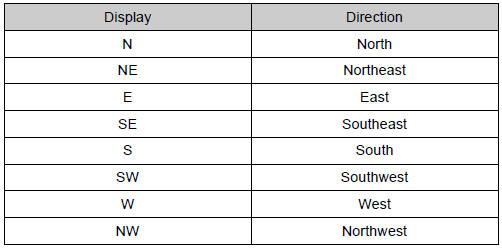
Displays and directions
 Compass
The compass on the inside rear view mirror indicates the direction
in which the vehicle is heading. ...
 Calibrating the compass
The direction display deviates from the true direction determined by
the earth’s magnetic field. The amount of deviation varies according to
the geographic position of the vehicle.
If you c ...
Other materials:
Pressure Control Solenoid "C" Performance (Shift
Solenoid Valve SL3)
SYSTEM DESCRIPTION
The ECM uses signals from the vehicle speed sensor to detect the actual gear
position (1st, 2nd, 3rd, 4th
or 5th gear).
Then the ECM compares the actual gear with the shift schedule in the ECM memory
to detect mechanical
troubles of the shift solenoid valves and valve bo ...
Sound Signal Circuit between Radio Receiver and Stereo Jack Adapter
DESCRIPTION
The stereo jack adapter sends an external device sound signal to the radio
receiver through this circuit.
The sound signal that has been sent is amplified by the stereo component
amplifier or radio receiver, and
then is sent to the speakers.
If there is an open or short in th ...
Removal
1. REMOVE FRONT WIPER ARM HEAD CAP
Using a small screwdriver, remove the 2 front wiper
arm covers.
HINT:
Tape up the screwdriver tip before use.
2. REMOVE FR WIPER ARM RH
Operate the wiper, and stop the windshield wiper
motor assembly to the automatic stop position.
...
