
Toyota Sienna Service Manual: Operation check
1. INPUT SIGNAL CHECK
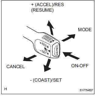
- Connect the intelligent tester to the DLC3.
- Check the cruise control main switch using the DATA LIST function in the intelligent tester (ONOFF, CANCEL, - (COAST)/SET, + (ACCEL)/RES (RESUME), and MODE).
2. INSPECT MODE SWITCH
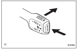
- Turn the ignition switch to the ON position.
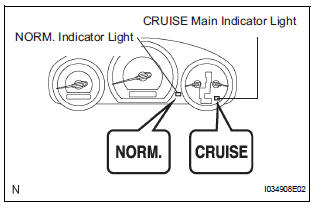
- Turn the cruise control main switch on. Then push the main switch to MODE for 1 second or more to change to the constant speed control mode. Check that "NORM." is indicated on the display.
NOTICE: Do not push any other switches before pushing the main switch to MODE. If another switch is pushed, turn the main switch off and repeat the procedure above. HINT: If a malfunction is detected, turn the ignition switch off and repeat the procedure above.
3. INSPECT STEERING PAD SWITCH ASSEMBLY
- Turn the ignition switch to the ON position.
- Turn the cruise control main switch on.
- Turn on the distance control switch of the steering pad switch.
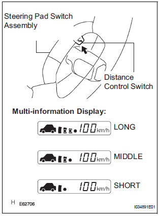
- Check that the indication of the vehicle-to-vehicle distance, which is shown on the multi-information display on the combination meter, changes from long to middle to short in that order.
HINT: The indication is automatically set to long each time the engine is started.
 Road test
1. PROBLEM SYMPTOM CONFIRMATION
HINT:
The dynamic laser cruise control system has two cruise
control modes: the constant speed control mode and
vehicle-to-vehicle distance control mode.
...
 Problem symptoms table
HINT:
Use the table below to help determine the cause of the
problem symptom. The likely causes of the problem are
indicated in descending order. Check each suspected area
in order. Re ...
Other materials:
Diagnosis system
1. CHECK DLC3
The vehicle's ECU uses ISO 15765-4 for
communication protocol. The terminal arrangement
of the DLC3 complies with SAE J1962 and matches
the ISO 15765-4 format.
NOTICE:
*: Before measuring the resistance, leave the
vehicle as is for at least 1 minute and do not
...
Rear combination light assembly
COMPONENTS
REMOVAL
1. DISCONNECT CABLE FROM NEGATIVE BATTERY
TERMINAL
2. REMOVE REAR COMBINATION LIGHT ASSEMBLY
Remove the 2 bolts.
Disengage the 2 pins and separate the rear
combination light assembly as shown in the
illustration.
Disconnect the connector a ...
Inspection
1. INSPECT MULTIPLE DISC CLUTCH HUB
(a) Using a dial indicator, measure the inside diameter
of the forward clutch hub bushing
Standard inside diameter:
23.025 to 23.046 mm (0.9065 to 0.9073 in.)
Maximum inside diameter:
23.09 mm (0.9091 in.)
NOTICE:
Check the contact surface of ...
