Toyota Sienna Service Manual: Oxygen Sensor Circuit
HINT:
Sensor 2 refers to the sensor mounted behind the Three-Way Catalytic Converter (TWC) and located far from the engine assembly.
DESCRIPTION
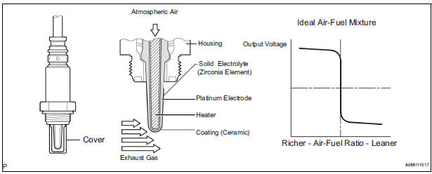
A three-way catalytic converter (TWC) is used in order to convert the carbon monoxide (CO), hydro carbon (HC), and nitrogen oxides (HOx) into less harmful substances. To allow the TWC to function effectively, it is necessary to keep the air-fuel ratio of the engine near the stoichiometric air-fuel ratio. For helping the ECM to deliver accurate air-fuel ratio control, a Heated Oxygen (HO2) sensor becomes used.
The HO2 sensor is located behind the TWC, and detects the oxygen concentration in the exhaust gas.
Since the sensor is integrated with the heater that heats the sensing portion, it is possible to detect the oxygen concentration even when the intake air volume is low (the exhaust gas temperature is low).
When the air-fuel ratio becomes lean, the oxygen concentration in the exhaust gas becomes rich. The HO2 sensor informs the ECM that the post-TWC air-fuel ratio is lean (low voltage, i.e. less than 0.45 V).
Conversely, when the air-fuel ratio is richer than the stoichiometric air-fuel level, the oxygen concentration in the exhaust gas becomes lean. The HO2 sensor informs the ECM that the post-TWC air-fuel ratio is rich (high voltage, i.e. more than 0.45 V). The HO2 sensor has the property of changing its output voltage drastically when the air-fuel ratio is close to the stoichiometric level.
The ECM uses the supplementary information from the HO2 sensor to determine whether the air-fuel ratio after the TWC is rich or lean, and adjusts the fuel injection time accordingly. Thus, if the HO2 sensor is working improperly due to internal malfunctions, the ECM is unable to compensate for deviations in the primary air-fuel ratio control.
MONITOR DESCRIPTION
Active Air-Fuel Ratio Control
The ECM usually performs air-fuel ratio feedback control so that the Air-Fuel Ratio (A/F) sensor output indicates a near stoichiometric air-fuel level. This vehicle includes active air-fuel ratio control in addition to regular air-fuel ratio control. The ECM performs active air-fuel ratio control to detect any deterioration in the Three-Way Catalytic Converter (TWC) and Heated Oxygen (HO2) sensor malfunctions (refer to the diagram below).
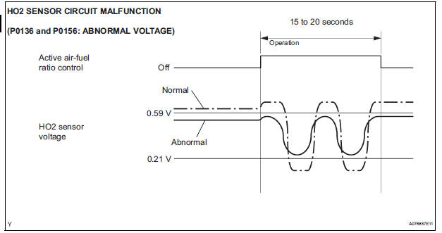
Active air-fuel ratio control is performed for approximately 15 to 20 seconds while driving with a warm engine. During active air-fuel ratio control, the air-fuel ratio is forcibly regulated to become lean or rich by the ECM.
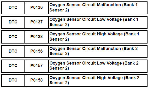
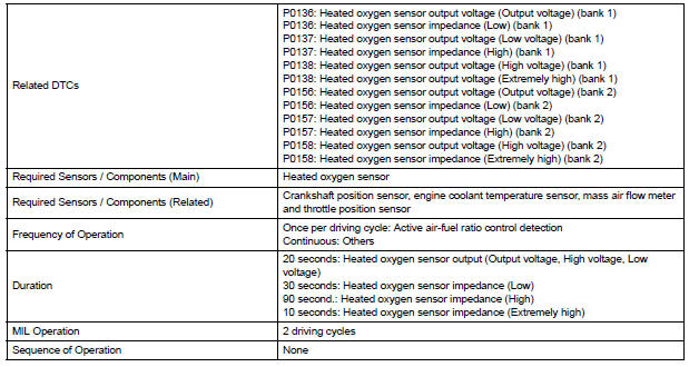
If the ECM detects a malfunction, one of the following DTCs is set: DTC P0136 or P0156 (abnormal voltage output), P0137 or P0157 (open circuit) or P0138 or P0158 (short circuit).
Abnormal Voltage Output of HO2 Sensor (DTCs P0136 and P0156)
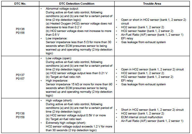
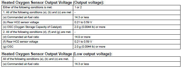
While the ECM is performing active air-fuel ratio control, the air-fuel ratio is forcibly regulated to become rich or lean. If the sensor is not functioning properly, the voltage output variation is small. For example, when the HO2 sensor voltage does not decrease to less than 0.21 V or does not increase to more than 0.59 V during active air-fuel ratio control, the ECM determines that the sensor voltage output is abnormal and sets DTCs P0136 and P0156.
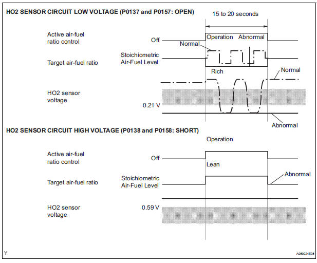
Open or Short in Heated Oxygen (HO2) Sensor Circuit (DTCs P0137 and P0157 or P0138 and P0158)
During active air-fuel ratio control, the ECM calculates the Oxygen Storage Capacity (OSC)* of the Three- Way Catalytic Converter (TWC) by forcibly regulating the air-fuel ratio to become rich or lean.
If the HO2 sensor has an open or short, or the voltage output of the sensor noticeably decreases, the OSC indicates an extraordinarily high value. Even if the ECM attempts to continue regulating the air-fuel ratio to become rich or lean, the HO2 sensor output does not change.
While performing active air-fuel ratio control, when the target air-fuel ratio is rich and the HO2 sensor voltage output is 0.21 V or less (lean), the ECM interprets this as an abnormally low sensor output voltage and sets DTC P0137 or P0157. When the target air-fuel ratio is lean and the voltage output is 0.59 V or more (rich) during active air-fuel ratio control, the ECM determines that the sensor voltage output is abnormally high, and sets DTC P0138 or P0158.
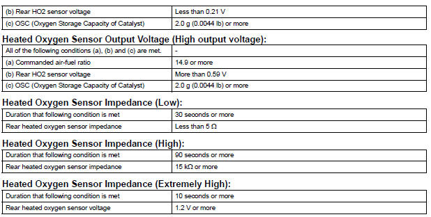
HINT: DTC P0138 or P0158 is also set if the HO2 sensor voltage output is more than 1.2 V for 30 seconds or more.
*: The TWC has the capability to store oxygen. The OSC and the emission purification capacity of the TWC are mutually related. The ECM determines whether the catalyst has deteriorated, based on the calculated OSC value (See page ES-250).
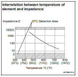
High or Low Impedance of Heated Oxygen (HO2) Sensor (DTCs P0136 and P0156 or P0137 and P0157)
During normal air-fuel ratio feedback control, there are small variations in the exhaust gas oxygen concentration. In order to continuously monitor the slight variation of the HO2 sensor signal while the engine is running, the impedance* of the sensor is measured by the ECM. The ECM determines that there is a malfunction in the sensor when the measured impedance deviates from the standard range.
*: The effective resistance in an alternating current electrical circuit.
HINT:
- The impedance cannot be measured using an ohmmeter.
- DTCs P0136 and P0156 indicate the deterioration of the HO2 sensor. The ECM sets the DTCs by calculating the impedance of the sensor when the typical enabling conditions are satisfied (1 driving cycle).
- DTCs P0137 and P0157 indicate an open or short circuit in the HO2 sensor (1 driving cycle). The ECM sets the DTCs when the impedance of the sensor exceeds the threshold 15 kΩ.
MONITOR STRATEGY
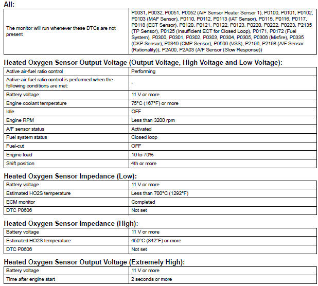
TYPICAL ENABLING CONDITIONS
TYPICAL MALFUNCTION THRESHOLDS
COMPONENT OPERATING RANGE

MONITOR RESULT
Refer to CHECKING MONITOR STATUS (See page ES-19).
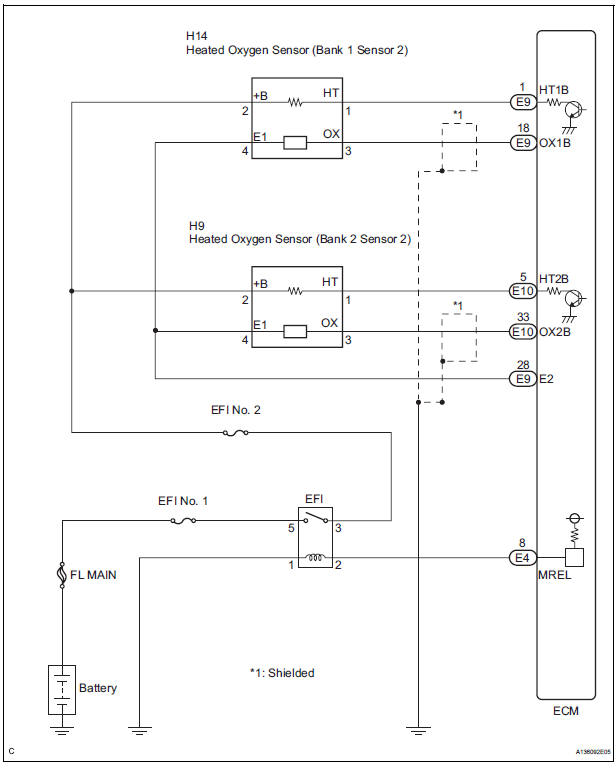
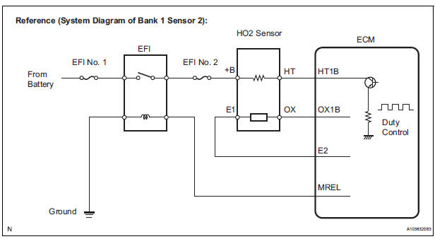
WIRING DIAGRAM
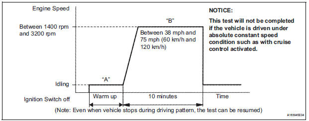
CONFIRMATION DRIVING PATTERN
HINT:
- This confirmation driving pattern is used in steps 5, 8 and 11 of the following diagnostic troubleshooting procedure when using the intelligent tester.
- Performing this confirmation pattern will activate the Heated Oxygen (HO2) sensor monitor. (The catalyst monitor is performed simultaneously.) This is very useful for verifying the completion of a repair.
1. Connect the intelligent tester to the DLC3.
2. Turn the ignition switch to the ON position.
3. Turn the tester on.
4. Clear the DTCs (where set) (See page ES-39).
5. Select the following menu items: DIAGNOSIS / CARB OBD II / READINESS TESTS.
6. Check that O2S EVAL is INCMPL (incomplete).
7. Start the engine and warm it up (Procedure A).
8. Drive the vehicle at between 38 mph and 75 mph (60 km/h and 120 km/h) for at least 10 minutes (Procedure B).
9. Note the state of the Readiness Tests items. Those items will change to COMPL (complete) as O2S EVAL monitor operates.
10.On the tester, select the following menu items: DIAGNOSIS / ENHANCED OBD II / DTC INFO / PENDING CODES and check if any DTCs (any pending DTCs) are set.
HINT: If O2S EVAL does not change to COMPL, and any pending DTCs fail to set, extend the driving time.
INSPECTION PROCEDURE
HINT: For use of the intelligent tester only: Malfunctioning areas can be identified by performing the A/F CONTROL function provided in the ACTIVE TEST. The A/F CONTROL function can help to determine whether the Air-Fuel Ratio (A/F) sensor, Heated Oxygen (HO2) sensor and other potential trouble areas are malfunctioning.
The following instructions describe how to conduct the A/F CONTROL operation using the intelligent tester.
1. Connect the intelligent tester to the DLC3.
2. Start the engine and turn the tester on.
3. Warm up the engine at an engine speed of 2500 rpm for approximately 90 seconds.
4. Select the following menu items on the tester: DIAGNOSIS / ENHANCED OBD II / ACTIVE TEST / A/F CONTROL.
5. Perform the A/F CONTROL operation with the engine in an idling condition (press the RIGHT or LEFT button to change the fuel injection volume).
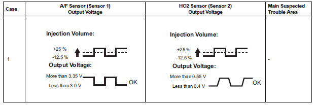
6. Monitor the voltage outputs of the A/F and HO2 sensors (AFS B1S1 and O2S B1S2 or AFS B2S1 and O2S B2S2) displayed on the tester.
HINT:
- The A/F CONTROL operation lowers the fuel injection volume by 12.5% or increases the injection volume by 25%.
- Each sensor reacts in accordance with increases and decreases in the fuel injection volume.
Standard voltage 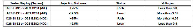
| NOTICE: The Air-Fuel Ratio (A/F) sensor has an output delay of a few seconds and the Heated Oxygen (HO2) sensor has a maximum output delay of approximately 20 seconds. |
- Following the A/F CONTROL procedure enables technicians to check the graph of the voltage outputs of both the A/F and HO2 sensors.
- To display the graph, select the following menu items on the tester: DIAGNOSIS / ENHANCED OBD II / ACTIVE TEST / A/F CONTROL / USER DATA / AFS B1S1 and O2S B1S2 or AFS B2S1 and O2S B2S2. Press the YES button and then the ENTER button. Then press the F4 button.
HINT:
- If other DTCs relating to different systems that have terminal E2 as the ground terminal are output simultaneously, terminal E2 may have an open circuit
- Read freeze frame data using the intelligent tester. The ECM records vehicle and driving condition information as freeze frame data the moment a DTC is stored. When troubleshooting, freeze frame data can be helpful in determining whether the vehicle was running or stopped, whether the engine was warmed up or not, whether the air-fuel ratio was lean or rich, as well as other data recorded at the time of a malfunction.
- If the OX1B wire from the ECM connector is short-circuited to the +B wire, DTC P0136 or P0156 will be set.
1 READ DTC OUTPUT
(a) Connect the intelligent tester to the DLC3.
(b) Turn the ignition switch to the ON position and turn the tester on.
(c) Select the following menu items: DIAGNOSIS / ENHANCED OBD II / DTC INFO / CURRENT CODES.
(d) Read the DTCs.
Result 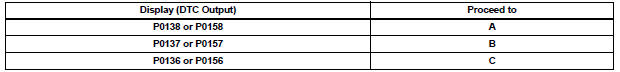

2 READ VALUE OF INTELLIGENT TESTER (OUTPUT VOLTAGE OF HEATED OXYGEN SENSOR)
(a) Connect the intelligent tester to the DLC3.
(b) Turn the ignition switch to the ON position and turn the tester on.
(c) Select the following menu items: DIAGNOSIS / ENHANCED OBD II / DATA LIST / PRIMARY / O2S B1S2 or O2S B2S2.
(d) Allow the engine to idle.
(e) Read the Heated Oxygen (HO2) sensor output voltage while idling.
Result 


3 CHECK HARNESS AND CONNECTOR (CHECK FOR SHORT)
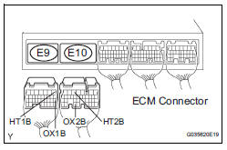
(a) Turn the ignition switch off and wait for 5 minutes.
(b) Disconnect the E9 or E10 ECM connectors.
(c) Measure the resistance according to the value(s) in the table below
Standard resistance 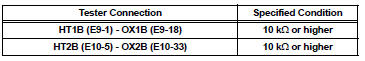
(d) Reconnect the ECM connectors.


REPLACE ECM (See page ES-498)
4 INSPECT HEATED OXYGEN SENSOR (CHECK FOR SHORT)
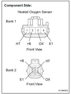
(a) Disconnect the H14 heated oxygen sensor connector (Bank 1 Sensor 2) or H9 heated oxygen sensor connector (Bank 2 Sensor 2).
(b) Measure the resistance according to the value(s) in the table below.
Standard resistance: 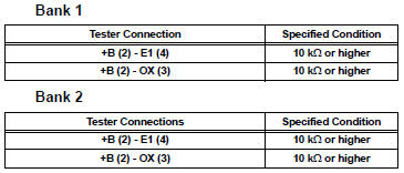
(c) Reconnect the HO2 sensor connectors.
Result 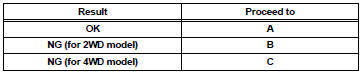

REPAIR OR REPLACE HARNESS OR CONNECTOR (HEATED OXYGEN SENSOR - ECM)
5 CHECK AIR FUEL RATIO SENSOR
HINT:
This A/F sensor test is to check the A/F sensor current during the fuel-cut. When the sensor is normal, the sensor current will indicate below 3 mA in this test.
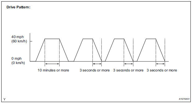
(a) Clear DTC.
(b) Drive the vehicle by the drive pattern as listed below:
(1) Warm up the engine.
(2) Drive the vehicle at 60 km/h (40 mph) or more for 10 minutes or more.
(3) Stop the vehicle.
(4) Accelerator the vehicle until 60 km/h (40 mph) or more and decelerate for 3 seconds or more.
Perform this three times.
(c) Enter the following menus: DIAGNOSIS / ENHANCED OBD ll / MONITOR INFO / MONITOR RESULT.
(d) Confirm that RANGE B1S1 is either PASS or FAIL.
(e) Select RANGE B1S1 an press ENTER.
(f) Read the test value.
Standard: Less than 3.0 mA
| NOTICE: Do not turn the engine switch Off during this step because the test results will be lost. |


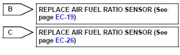
REPLACE AIR FUEL RATIO SENSOR
6 READ VALUE USING INTELLIGENT TESTER (OUTPUT VOLTAGE OF HEATED OXYGEN SENSOR)
(a) Connect the intelligent tester to the DLC3.
(b) Turn the ignition switch ON and turn the tester ON.
(c) Start the engine.
(d) Select the following menu items: DIAGNOSIS / ENHANCED OBD ll / DATA LIST / PRIMARY / O2S B1 S2 or O2S B2 S2.
(e) After warming up the engine, run the engine at an engine speed of 2500 rpm for 3 minutes.
(f) Read the output voltage of the HO2 sensor when the engine rpm is suddenly increased.
HINT:
Quickly accelerate the engine to 4000 rpm 3 times using the accelerator pedal.
Standard voltage : Fluctuates between 0.4 V or less and 0.5 V or more.


7 PERFORM CONFIRMATION DRIVING PATTERN

8 CHECK WHETHER DTC OUTPUT RECURS (DTC P0136 OR P0156)
(a) On the intelligent tester, select the following menu items: DIAGNOSIS / ENHANCED OBD ll / DTC INFO / CURRENT CODES.
(b) Read DTCs.
Result 

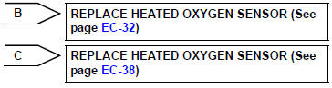
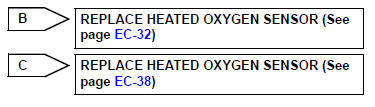
9 REPLACE HEATED OXYGEN SENSOR

10 PERFORM CONFIRMATION DRIVING PATTERN

11 CHECK WHETHER DTC OUTPUT RECURS (DTC P0136 OR P0156)
(a) On the intelligent tester, select the following menu items: DIAGNOSIS / ENHANCED OBD ll / DTC INFO / CURRENT CODES.
(b) Read DTCs.
Result 

12 PERFORM ACTIVE TEST BY INTELLIGENT TESTER (INJECTION VOLUME)
(a) Connect the intelligent tester to the DLC3.
(b) Start the engine and turn the tester on.
(c) Warm up the engine.
(d) Select the following menu items: DIAGNOSIS / ENHANCED OBD II / ACTIVE TEST / INJ VOL.
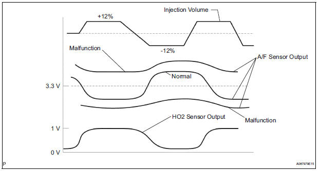
(e) Change the fuel injection volume using the tester, while monitoring the voltage output of Air-Fuel Ratio (A/F) and HO2 sensors displayed on the tester.
HINT:
- Change the fuel injection volume within the range of - 12% and +12%. The injection volume can be changed in 1% graduations within the range.
- The A/F sensor is displayed as AFS B1S1 or AFS B2S1, and the HO2 sensor is displayed as O2S B1S2 or O2S B2S2, on the intelligent tester.
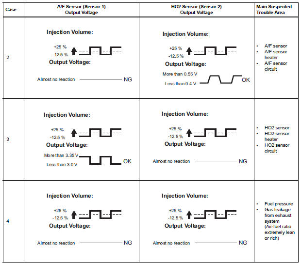
Result 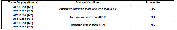
HINT:
A normal HO2 sensor voltage (O2S B1S2 or O2S B2S2) reacts in accordance with increases and decreases in fuel injection volumes. When the A/F sensor voltage remains at either less or more than 3.3 V despite the HO2 sensor indicating a normal reaction, the A/F sensor is malfunctioning.
Result 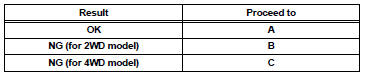

CHECK AND REPLACE EXTREMELY RICH OR LEAN ACTUAL AIR FUEL RATIO (INJECTOR, FUEL PRESSURE, GAS LEAKAGE FROM EXHAUST SYSTEM)
13 INSPECT FOR EXHAUST GAS LEAK
OK: No gas leakage.

14 INSPECT HEATED OXYGEN SENSOR (HEATER RESISTANCE)
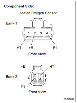
(a) Disconnect the H14 heated oxygen sensor connector (Bank 1 Sensor 2) or H9 heated oxygen sensor connector (Bank 2 Sensor 2).
(b) Measure the resistance according to the value(s) in the table below.
Standard resistance: 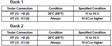
(c) Reconnect the HO2 sensor connectors.
Result 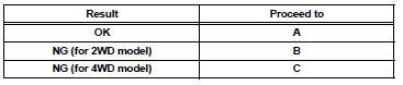

15 INSPECT RELAY (EFI RELAY)
(a) Remove the EFI relay from the engine room J/B.
(b) Measure the resistance according to the value(s) in the table below.
Standard resistance 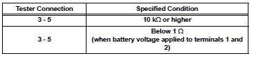
(c) Reinstall the relay.

16 CHECK HARNESS AND CONNECTOR (HEATED OXYGEN SENSOR - ECM)
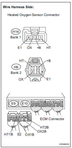
(a) Disconnect the H14 or H9 HO2 sensor connector.
(b) Turn the ignition switch to the ON position.
(c) Measure the voltage according to the value(s) in the table below.
Standard voltage 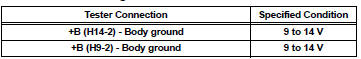
(d) Turn the ignition switch off.
(e) Disconnect the E9 and E10 ECM connectors.
(f) Measure the resistance according to the value(s) in the table below.
Standard resistance: 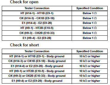
(g) Reconnect the HO2 sensor connectors.
(h) Reconnect the ECM connectors.
Result 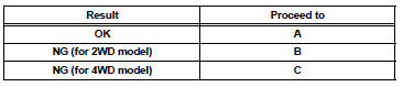

REPAIR OR REPLACE HARNESS OR CONNECTOR (HEATED OXYGEN SENSOR - ECM)
 Coolant Thermostat (Coolant Temperature Below Thermostat Regulating
Temperature)
Coolant Thermostat (Coolant Temperature Below Thermostat Regulating
Temperature)
HINT:
This DTC relates to the thermostat.
DESCRIPTION
This DTC is set when the Engine Coolant Temperature (ECT) does not reach 75°C
(167°F) despite
sufficient engine warm-up time.
MON ...
 System Too
DESCRIPTION
The fuel trim is related to the feedback compensation value, not to the basic
injection time. The fuel trim
consists of both the short-term and long-term fuel trims.
The short-ter ...
Other materials:
Brake fluid
Bleeding
HINT:
If any work is performed on the brake system or if air in the
brake lines is suspected, bleed the air out of the brake
system.
NOTICE:
Wash the brake fluid off immediately if it adheres to any
painted surfaces.
1. REMOVE COWL TOP PANEL SUB-ASSEMBLY
OUTER FRONT (See page SP-13 ...
Fuel sender gauge
assembly
INSPECTION
1. INSPECT FUEL SENDER GAUGE ASSEMBLY
Disconnect the connector from the fuel sender
gauge.
Check that the float moves smoothly between F and
E.
Measure the resistance between terminals 1 and 2
of the connector according to the value(s) in the
table b ...
Correct driving posture
Adjust the angle of the seatback so that you are sitting straight up and
so that you do not have to lean forward to steer.
Adjust the seat so that you can depress the pedals fully and so that
your arms bend slightly at the elbow when gripping the steering wheel.
Lock the head rest ...
