Toyota Sienna Service Manual: Parking Brake Switch Circuit
DESCRIPTION
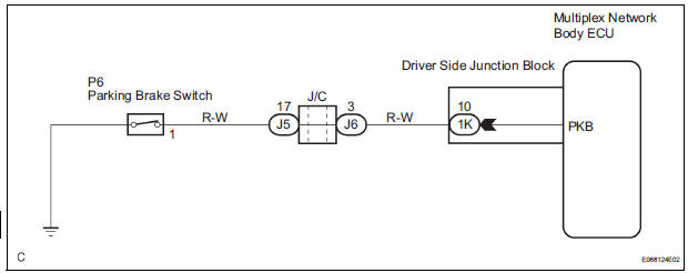
The Multiplex network body ECU receives parking brake switch signal.
WIRING DIAGRAM
INSPECTION PROCEDURE
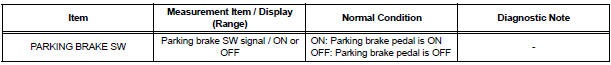
1 READ VALUE OF INTELLIGENT TESTER
- Connect the intelligent tester to DLC3.
- Turn the ignition switch ON and push the intelligent tester main switch ON.
- Select the items below in the DATA LIST, and read the displays on the intelligent tester.
BODY NO.1:
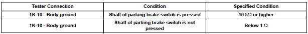
2 INSPECT PARKING BRAKE SWITCH ASSEMBLY
- Check that there is resistance between the terminal and the body ground when parking brake switch is operated.
Resistance:
ON (When shaft is pressed): No continuity:
10 kΩ or higher
OFF (When shaft is not pressed): Continuity:
Below 1 Ω
3 CHECK HARNESS AND CONNECTOR
- Disconnect the 1K connector from instrument panel junction block assembly
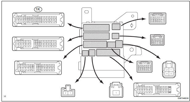
- Check the resistance between the terminal 1K-10 of the instrument panel junction block assembly connector side and body ground
PROCEED TO NEXT CIRCUIT INSPECTION SHOWN IN PROBLEM SYMPTOMS TABLE
 Illumination Circuit
DESCRIPTION
The Multiplex network body ECU controls illumination light as shown in the
chart below.
Room light assembly (Interior light, luggage component light) and
courtesy light wit ...
 Taillight Relay Circuit
DESCRIPTION
The Multiplex network body ECU controls TAIL relay when signal is received
from headlight dimmer
switch assembly.
WIRING DIAGRAM
INSPECTION PROCEDURE
1 PERFORM ACTIVE TEST BY IN ...
Other materials:
Installation
1. INSTALL TRANSFER EXTENSION HOUSING TYPE T OIL SEAL
(a) Using SST(s), install anew transfer extension
housing type T oil seal to he transfer extension
housing sub-assembly at the position show in the
illustration.
SST 09325-20010
NOTICE:
Do not install the oil seal obliquely.
(b) Apply ...
Removal
1. REMOVE BACK DOOR CENTER GARNISH (See page
ET-18)
2. REMOVE POWER BACK DOOR ROD (See page ED-
220)
3. REMOVE BACK DOOR LH SIDE GARNISH
4. REMOVE BACK DOOR RH SIDE GARNISH
5. REMOVE BACK DOOR PULL STRAP (See page ED-
221)
6. REMOVE BACK DOOR TRIM BOARD ASSEMBLY
7. REMOVE LH BACK-UP LIGH ...
Transponder Chip Malfunction
DTC B2793 Transponder Chip Malfunction
DESCRIPTION
This DTC is output when a malfunction is found in the key during the key code
registration or the key code
is not registered normally. Replace the key when the key code registration is
not performed normally and
this DTC is detected.
IN ...
