Toyota Sienna Service Manual: Parking Brake Switch Circuit
DESCRIPTION
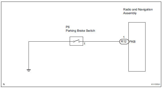
This circuit is from the parking brake switch to the radio and navigation assembly.
WIRING DIAGRAM
INSPECTION PROCEDURE
1 CHECK BRAKE WARNING LIGHT
- Check that the brake warning light comes on when the parking brake is applied and goes off when it is released.
OK: The brake warning light operates as specified above.
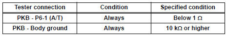
2 INSPECT PARKING BRAKE SWITCH
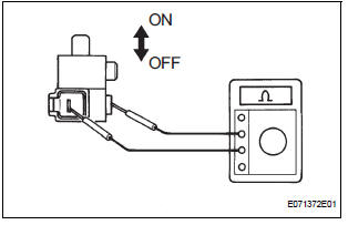
- Disconnect the parking brake switch.
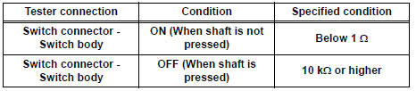
- Measure the resistance according to the value(s) in the table below.
Standard resistance
3 CHECK HARNESS AND CONNECTOR (PARKING BRAKE SWITCH - RADIO AND NAVIGATION ASSEMBLY)
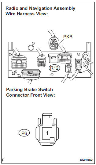
- Disconnect the radio and navigation assembly connector R12 and parking brake switch connector P6.
- Measure the resistance according to the value(s) in the table below.
Standard resistance
PROCEED TO NEXT CIRCUIT INSPECTION SHOWN IN PROBLEM SYMPTOMS TABLE
 Illumination Circuit
DESCRIPTION
Power is supplied to the radio and navigation assembly and steering pad
switch illumination when the
light control switch is in the TAIL or HEAD position.
WIRING DIAGRAM
INSPECTI ...
 Speaker Circuit
DESCRIPTION
The sound signal that has been amplified by the stereo component amplifier is
sent to the speakers from
the stereo component amplifier through this circuit.
If there is a short in t ...
Other materials:
Inspection
1. INSPECT PARK/NEUTRAL POSITION SWITCH ASSEMBLY OPERATION
(a) Apply the parking brake and turn the ignition switch
to the ON position.
(b) Depress the brake pedal and check that the engine
starts only when the shift lever is in the N or P
position and the engine does not start when the shift ...
Headlight dimmer switch
COMPONENTS
REMOVAL
1. REMOVE STEERING COLUMN LOWER COVER
2. REMOVE STEERING COLUMN UPPER COVER
3. REMOVE HEADLIGHT DIMMER SWITCH ASSEMBLY
Disconnect the connector.
Release the claw fitting and remove the headlight
dimmer switch assembly.
INSPECTION
1. HEADLIGHT DI ...
Speed sensor check (when using sst check wire)
(a) Check the speed sensor signal.
(1) Drive the vehicle straight forward. Drive the
vehicle at a speed of 45 km/h (28 mph) or higher
for several seconds and check that the ABS
warning light goes off.
HINT:
The signal check may not be completed if the
vehicle has its wheels spun or the stee ...
