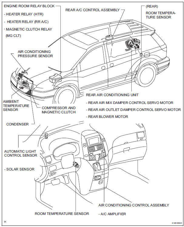
Toyota Sienna Service Manual: Parts location
HOW TO PROCEED WITH TROUBLESHOOTING
1 VEHICLE BROUGHT TO WORKSHOP

2 CUSTOMER PROBLEM ANALYSIS
(a) Confirm problem symptoms.

3 CHECK AND CLEAR DTCS

4 PROBLEM SYMPTOM CONFIRMATION
5 SYMPTOM SIMULATION

6 DTC CHECK (OTHER THAN MULTIPLEX DTC)
7 DTC CHART
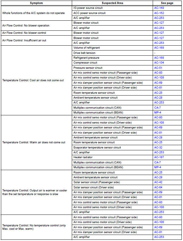
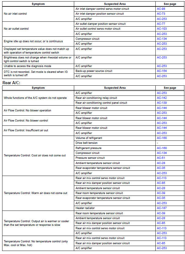
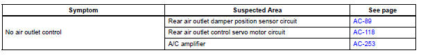
8 PROBLEM SYMPTOMS TABLE

9 TERMINALS OF ECU

10 CIRCUIT INSPECTION

11 IDENTIFICATION OF PROBLEM

12 REPAIR OR REPLACE

13 CONFIRMATION TEST

END
Problem symptoms table
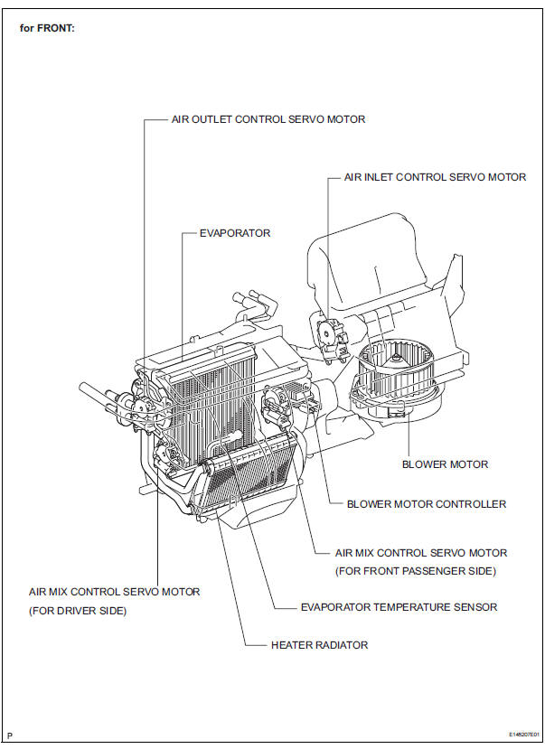
Front A/C:
 Precaution
NOTICE:
Because the compressor operates at high voltages, wear
electric insulated gloves and pull out the service plug to
cut the high-voltage circuit before inspection.
1. DO NOT HANDLE REFRIGERA ...
 Terminals of ecu
1. A/C AMPLIFIER
(a) Waveform 1:
(b) Waveform 2:
(c) Waveform 3: ...
Other materials:
Removal
1. REMOVE INSTRUMENT CLUSTER FINISH PANEL
CENTER NO.1 (See page IP-8)
2. REMOVE INSTRUMENT CLUSTER FINISH PANEL
CENTER NO.2
3. REMOVE SHIFT LEVER KNOB SUB-ASSEMBLY
HINT:
(See page AX-146 for U151E, AX-146 for U151F)
4. REMOVE INSTRUMENT CLUSTER FINISH PANEL
ASSEMBLY CENTER (See page IP-9)
5 ...
Active Control Engine Mount System
DESCRIPTION
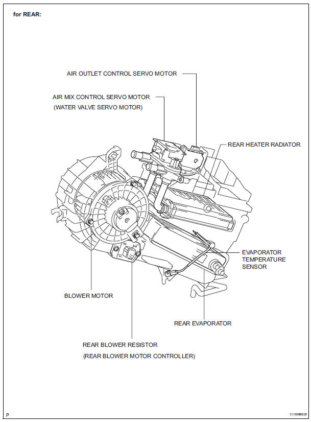
LOCATION
The Active Control Engine Mount (ACM) system decreases engine vibration at
engine idling using the
ACM VSV. The VSV is controlled by a pulse signal transmitted to the VSV from the
ECM. The frequency
of this pulse signal is matched to the engine speed to decrease engine ...
Indicator Circuit
DESCRIPTION
This system has two indicator lights. One of the indicator lights is built
into the fold seat switch. This
indicator light receives power from the fold seat control ECU. It comes on or
blinks when the system
detects that an object is caught or when the seat operation conditions ar ...
