
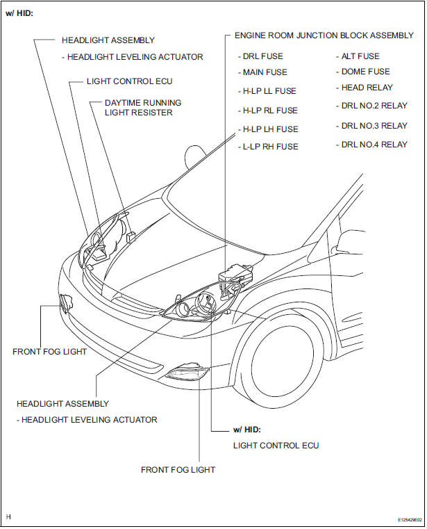
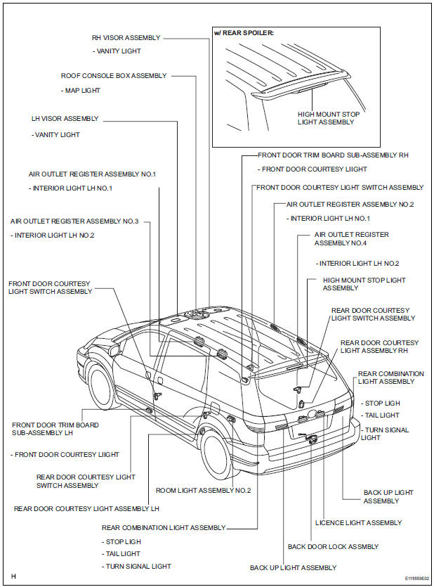
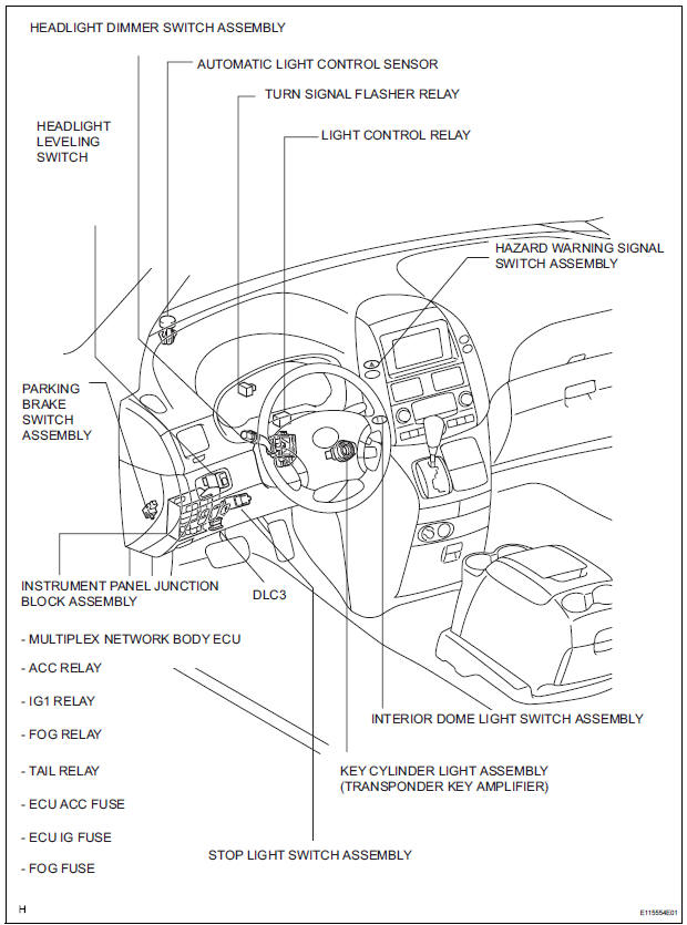
Toyota Sienna Service Manual: Parts location
 Precaution
1. PRECAUTION OF HEADLIGHT BULB
REPLACEMENT
When any defects such as deformation, crack, dent,
chipping, etc. are identified on the discharge
headlight (especially, on the light control ...
 How to proceed with
troubleshooting
How to proceed with
troubleshooting
1 VEHICLE BROUGHT TO WORK SHOP
2 CUSTOMER PROBLEM ANALYSIS
3 CHECK BODY MULTIPLEX COMMUNICATION SYSTEM
Check for the DTC outputs.
4 DTC CHECK
5 DTC CHART
6 PROBLEM SYMPTOMS TABLE
7 TERMINA ...
Other materials:
Hydraulic test
1. Perform hydraulic test
(a) Measure the line pressure.
NOTICE:
Perform the test at the normal operating ATF
(Automatic Transmission Fluid) temperature:
50 to 80°C (122 to 176°F).
The line pressure test should always be
carried out in pairs. One technician should
...
Rear Air Mix Damper Control Servo Motor Circuit
DESCRIPTION
The rear air mix control servo motor (water valve servo motor) is controlled
by the A/C amplifier.
The rear air mix control servo motor moves the air mix damper by rotating
(normal, reverse) with electrical
power from the A/C amplifier.
WIRING DIAGRAM
INSPECTION PROCEDURE
...
Screen Flicker or Color Distortion
INSPECTION PROCEDURE
1 CHECK DISPLAY SETTING
Enter the display adjustment screen by pressing the
"DISPLAY" switch.
Reset display settings (contrast, brightness) and check
that the screen appears normal
Press the "INFO" switch and then select "S ...
