Toyota Sienna Service Manual: Perform signal check
HINT:
- When entering signal check mode, the tire pressure
warning ECU sets all the signal check DTCs first.
After completing signal check for each inspection item, the DTCs for systems that are determined to be normal by the tire pressure warning ECU will be erased.
The DTCs for other inspection items may not be erased when only a certain signal is inspected.
- When signal check returns to normal mode, all the signal check DTCs will be erased.
(a) Make sure that the ignition switch is off.
(b) Connect the intelligent tester to DLC3.
(c) Turn the ignition switch to the ON position.
(d) Select the SIGNAL CHECK on the intelligent tester.
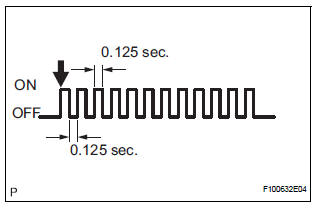
HINT: Every time the test mode DTC clear conditions are satisfied, the tire pressure warning light comes on for 1 second. Then, the tire pressure warning light blinks at 0.125-second intervals.
(e) Drive the vehicle at 12 mph (20 km/h) or more for 10 seconds or more to check the vehicle speed signal (C2191/91).
(f) Loosen the valve core and rapidly reduce the pressure (at least 40 kPa (0.41 kg/cm2, 5.8 psi) within 30 seconds or more) to check the transmitter data (C2181/81 to C2184/84).
HINT: The transmitter ID can be transmitted by rapidly reducing the tire pressure.
(g) Check that the tire pressure warning system test
mode DTCs are erased.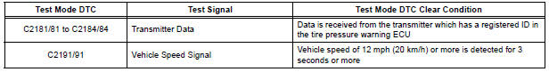
(h) Check the tire pressure warning reset switch.
(1) Press the tire pressure warning reset switch.
(2) Check the tire pressure warning indicator light.
(i) Result
HINT:
After the signal check is completed, check for a
signal check DTC to confirm the system status
(j) End of SIGNAL CHECK
After completing the test mode (SIGNAL CHECK), turn the ignition switch off and disconnect the tester.
DTC of SIGNAL CHECK (TEST DIAGNOSIS)
function:
If a trouble code is displayed during the test mode
DTC check, check the circuit listed for that code. For
details of each code, refer to the relevant page listed
under respective "DTC No." in the chart.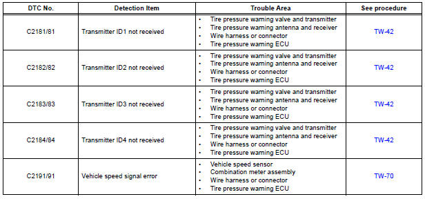
 Enter test mode
HINT:
Operation of the tire pressure warning reset switch
can be checked in TEST MODE.
During TEST MODE, the system is not initialized by
pushing the tire pressure warning reset switch. The
...
 Problem symptoms table
HINT:
Use the table below to help determine the cause of the
problem symptom. The potential causes of the symptoms
are listed in order of probability in the "Suspected Area"
column ...
Other materials:
Air conditioning controls
Adjusting the temperature setting
Turn the “TEMP” dial clockwise to increase the temperature and
counterclockwise to decrease the temperature.
The “SYNC” button
The air conditioning system switches between individual (indicator(
s) off) and simultaneous (indicators on) modes.
Whe ...
Fail-safe chart
HINT:
If the following conditions are detected while the cruise
control is in operation, the system clears the stored vehicle
speed in the ECM and cancels the cruise control operation.
Vehicle Condition
Auto Cancel Condition
Re-operation Condition
CRUISE main in ...
Precaution
NOTICE:
When the ignition switch is turned off and the engine
temperature is high, the cooling fans may operate for
approximately 3 minutes.
After turning the ignition switch off, keep hands and
objects away from the fans when they are operating.
HINT:
If al ...
