Toyota Sienna Service Manual: Perform zero point calibration of yaw rate and deceleration sensor (when using sst check wire)
NOTICE:
- While obtaining the zero point, do not vibrate the vehicle by tilting, moving or shaking it and keep it in a stationary condition. (Do not turn the ignition switch to the ON position.)
- Be sure to do this on a level surface (with an inclination of less than 1 %).
(a) Procedures for test mode.
(1) Check that the steering wheel is in the straightahead position and move the shift lever to the P position and apply the parking brake.
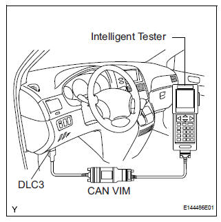
(2) Connect the intelligent tester to the DLC3.
(3) Turn the ignition switch to the ON position.
(4) Set the intelligent tester to test mode (select "TEST MODE").
HINT: Refer to the intelligent tester operator's manual for further details.
(b) Obtain the zero point of the yaw rate and deceleration sensor.
(1) Keep the vehicle in the stationary condition on a level surface for 2 seconds or more.
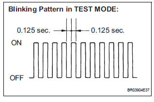
(2) Check that the ABS warning light and VSC warning light blink.
HINT:
- If the ABS warning light and VSC warning light do not blink perform zero point calibration again.
- The zero point calibration is performed only once after the system enters the test mode.
- Calibration cannot be performed again until the stored data is cleared once.
(c) Turn the ignition switch off and disconnect the intelligent tester.
PERFORM ZERO POINT CALIBRATION OF YAW RATE AND DECELERATION SENSOR (WHEN USING SST CHECK WIRE):
NOTICE:
- While obtaining the zero point, do not vibrate the vehicle by tilting, moving or shaking it and keep it in a stationary condition. (Do not turn the ignition switch to the ON position.)
- Be sure to do this on a level surface (with an inclination of less than 1 %).
(a) Clear the zero point calibration.
(1) Turn the ignition switch to the ON position.
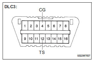
(2) Using SST, connect and disconnect terminals TS and CG of the DLC3 4 times or more within 8 seconds.
SST 09843-18040
(b) Procedures for test mode.
(1) Turn the ignition switch off.
(2) Using SST, connect terminals TS and CG of the DLC3.
SST 09843-18040
(3) Check that the steering wheel is in the straightahead position and move the shift lever to the P position.
(c) Obtain the zero point of the yaw rate and deceleration sensor.
(1) Turn the ignition switch to the ON position.
(2) Keep the vehicle in a stationary condition on a level surface for 2 seconds or more.
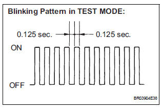
(3) Check that the ABS warning light and VSC light blink (test mode).
HINT:
- If the ABS warning light and VSC warning light do not blink perform zero point calibration again.
- The zero point calibration is performed only once after the system enters the test mode.
- Calibration cannot be performed again until the stored data is cleared once.
(d) Turn the ignition switch off and disconnect the SST from the DLC3.
 Perform zero point calibration of yaw rate and deceleration sensor (when
using intelligent tester)
Perform zero point calibration of yaw rate and deceleration sensor (when
using intelligent tester)
(a) Connect the intelligent tester to the DLC3.
(b) Turn the ignition switch to the ON position.
(c) Operate the intelligent tester to erase the codes
(select "RESET MEMORY").
...

Other materials:
Power slide door main switch
INSPECTION
1. INSPECT POWER SLIDE DOOR MAIN SWITCH
Inspect the resistance of the switch.
Resistance
If the result is not as specified, replace the switch.
Apply battery voltage and check the illuminates.
Standard
HINT:
Whether the switch illuminates or not will not affect
...
Display Signal Circuit between Video Terminal and Television Display
DESCRIPTION
This is the display signal circuit from the video terminal to the television
display assembly.
WIRING DIAGRAM
INSPECTION PROCEDURE
1 CHECK HARNESS AND CONNECTOR (TELEVISION DISPLAY ASSEMBLY - VIDEO
TERMINAL)
Disconnect the connectors from the video terminal and
tele ...
Sound Signal Circuit between Video Terminal and Television Display
DESCRIPTION
This is the sound signal circuit from the video (video adapter) terminal to
the television display assembly.
WIRING DIAGRAM
INSPECTION PROCEDURE
1 CHECK HARNESS AND CONNECTOR (TELEVISION DISPLAY ASSEMBLY - VIDEO
TERMINAL)
Disconnect the connectors from the video (vide ...
