Toyota Sienna Service Manual: Power steering fluid
Bleeding
1. BLEED POWER STEERING SYSTEM
(a) Check the fluid level (See page PS-2).
(b) Jack up the front of the vehicle and support it with stands.
(c) Turn the steering wheel.
(1) With the engine stopped, turn the steering wheel slowly from lock to lock several times.
(d) Lower the vehicle.
(e) Start the engine.
(1) Run the engine at idle for a few minutes.
(f) Turn the steering wheel.
(1) With the engine idling, turn the steering wheel left or right to the full lock position and keep it in that position for 2 to 3 seconds, then turn the steering wheel to the opposite full lock position and keep it there for 2 to 3 seconds.
(2) Repeat this procedure several times.
(g) Stop the engine.
(h) Check for foaming or emulsification.
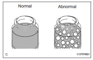
HINT: If the system has to be bled twice because of forming or emulsification, be sure to check for fluid leaks in the system.
(i) Check the fluid level (See page PS-2).
 On-vehicle inspection
1. INSPECT DRIVE BELT
(a) Visually check the drive belt for excessive wear,
frayed cords, etc.
If any defect is found, replace the drive belt.
HINT:
Cracks on the rib side of a belt are con ...
 Vane pump
COMPONENTS
...
Other materials:
Changing the rear setting
Adjusting the temperature setting
Press the “REAR” button (indicator and rear temperature on the
display on).
Turn the “REAR TEMP” dial clockwise to increase the temperature
and counterclockwise to decrease the temperature.
The air conditioning system switches between individual ...
Canceling the power sliding door system (vehicles with power
sliding doors)
Turn the main switch off to disable
the power sliding door system.
Off
The sliding doors can only be
opened and closed manually.
On*
The power sliding door can be
opened and closed with the power
sliding door switches for the front
occupants or wireless remote control
even if ...
Installation
1. INSTALL STEERING PAD
Support the steering pad with one hand as shown in
the illustration.
Connect the 2 connectors to the steering pad.
NOTICE:
When handling the airbag connector, take care
not to damage the airbag wire harness.
Connect the horn connector.
...
