Toyota Sienna Service Manual: Precaution
1. INSPECTION PROCEDURE FOR VEHICLE INVOLVED IN ACCIDENT
- Perform the zero point calibration and sensitivity check if any of the following conditions occur.
- The occupant classification ECU is replaced.
- Accessories (seatback tray and seat cover, etc.) are installed.
- The front passenger seat is removed from the vehicle.
- The passenger airbag ON/OFF indicator ("OFF") comes on when the front passenger seat is not occupied.
- The vehicle is brought to the workshop for repair due to an accident or a collision.
NOTICE: When an accident vehicle is brought into the workshop for repair, check the flatness of the body side that is equipped with the passenger seat. If the flatness is not within +- 3.0 mm (0.118 in.), adjust it to the specified range.
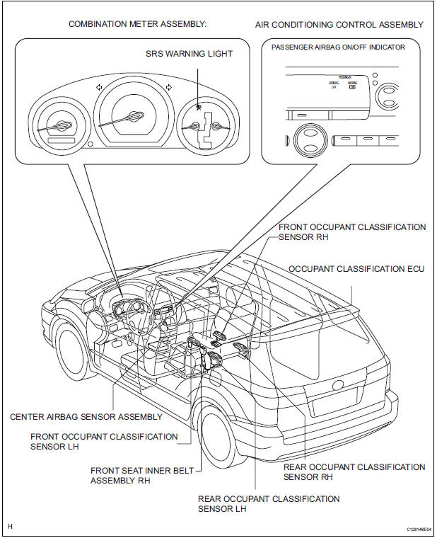
PARTS LOCATION
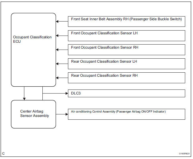
SYSTEM DIAGRAM

 System description
1. DESCRIPTION OF OCCUPANT CLASSIFICATION SYSTEM
GENERAL DESCRIPTION.
In the occupant classification system, the
occupant classification ECU calculates the
weight of the occu ...
Other materials:
Adjustment
HINT:
On the RH side, use the same procedures as on the LH side.
1. INSPECT SLIDE DOOR PANEL SUB-ASSEMBLY LH
Check that the clearance is within the standard
range.
Standard
2. ADJUST SLIDE DOOR PANEL SUB-ASSEMBLY LH
Using the SST, horizontally and vertically adjust the
...
Power Slide Door LH does not Operate When Satellite Switch is
Pressed
DESCRIPTION
The power slide door operates only when the power slide door main
switch is ON (switch free: orange
paint on the top of the switch appears). The power slide door ECU LH
controls the power slide door LH,
which activates the slide door motor to open / close the slide do ...
On-vehicle inspection
1. INSPECT REAR AXLE HUB BEARING BACKLASH
(a) Using a dial gauge, check for backlash near the
center of the axle hub.
Maximum:
0.05 mm (0.0020 in.)
If backlash exceeds the maximum, replace the axle
hub assembly.
NOTICE:
Ensure that the dial gauge is set at right angles
to the measuremen ...
